Product Description
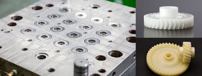
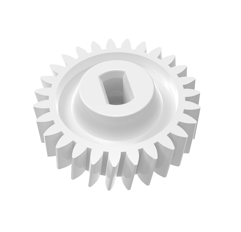
IHF OEM Customized High Precision Plastic Gear For CNC Machining
Main Features:
Helical Gear
1. Produce strictly in accordance with ANSI or DIN standard dimension
2. Material: 1045 Carbon Steel
3. Bore: Finished bore
4. Module: 1~3
Product Parameters
| Product name | Spur Gear & Helical Gear & Gear Shaft |
| Customized service | OEM, drawings or samples customize |
| Materials Available | Stainless Steel, Carbon Steel, S45C, SCM415, 20CrMoTi, 40Cr, Brass, SUS303/304, Bronze, Iron, Aluminum Alloy etc |
| Heat Treatment | Quenching & Tempering, Carburizing & Quenching, High-frequency Hardening, Carbonitriding…… |
| Surface Treatment | Conditioning, Carburizing and Quenching,Tempering ,High frequency quenching, Tempering, Blackening, QPQ, Cr-plating, Zn-plating, Ni-plating, Electroplate, Passivation, Picking, Plolishing, Lon-plating, Chemical vapor deposition(CVD), Physical vapour deposition(PVD)… |
| BORE | Finished bore, Pilot Bore, Special request |
| Processing Method | Molding, Shaving, Hobbing, Drilling, Tapping, Reaming, Manual Chamfering, Grinding etc |
| Pressure Angle | 20 Degree |
| Hardness | 55- 60HRC |
| Size | Customer Drawings & ISO standard |
| Package | Wooden Case/Container and pallet, or made-to-order |
| Certificate | ISO9001:2008 |
| Machining Process | Gear Hobbing, Gear Milling, Gear Shaping, Gear Broaching, Gear Shaving, Gear Grinding and Gear Lapping |
| Applications | Printing Equipment Industry, Laser Equipment Industry, Automated Assemblyline Industry, Woodening Industry, Packaging Equipment Industry, Logistics storage Machinery Industry, Robot Industry, Machine Tool Equipment Industry |
Company Profile
Packaging & Shipping
FAQ
| Main Markets? | North America, South America, Eastern Europe , West Europe , North Europe, South Europe, Asia |
| How to order? | * You send us drawing or sample |
| * We carry through project assessment | |
| * We give you our design for your confirmation | |
| * We make the sample and send it to you after you confirmed our design | |
| * You confirm the sample then place an order and pay us 30% deposit | |
| * We start producing | |
| * When the goods is done, you pay us the balance after you confirmed pictures or tracking numbers. | |
| * Trade is done, thank you!! |
If you are interested in our products, please tell us which materials, type, width, length u want.
/* January 22, 2571 19:08:37 */!function(){function s(e,r){var a,o={};try{e&&e.split(“,”).forEach(function(e,t){e&&(a=e.match(/(.*?):(.*)$/))&&1
| Condition: | New |
|---|---|
| Certification: | RoHS, ISO9001 |
| Standard: | DIN, GB, JIS |
| Customized: | Customized |
| Material: | Stainless Steel |
| Application: | Metal Cutting Machine, Metal Straightening Machinery, Metal Processing Machinery Parts, Metal forging Machinery, Metal Engraving Machinery, Metal Drawing Machinery, Metal Casting Machinery |
| Samples: |
US$ 15/Piece
1 Piece(Min.Order) | |
|---|
| Customization: |
Available
| Customized Request |
|---|
Can plastic gears be used in food and beverage processing machinery?
Plastic gears can be used in food and beverage processing machinery in certain applications. Here’s a detailed explanation of their suitability:
Plastic gears offer several advantages that make them a viable choice for certain food and beverage processing machinery applications:
- Corrosion Resistance: Many plastic materials, such as certain types of polypropylene (PP) or polyethylene (PE), exhibit excellent resistance to corrosion and chemical attack. This makes them suitable for use in food and beverage processing environments where exposure to acidic or alkaline substances, cleaning agents, or food ingredients is common.
- Hygienic Properties: Plastic gears can be designed to have smooth surfaces without any cracks, crevices, or pores, which can harbor bacteria or contaminants. This makes them easier to clean and sterilize, promoting hygienic conditions in food and beverage processing machinery.
- Lightweight: Plastic gears are generally lighter than metal gears, which can be advantageous in applications where weight reduction is desired. The reduced weight can simplify machinery design, reduce energy consumption, and ease handling during maintenance or equipment assembly.
- Noise Reduction: Plastic gears, with their inherent damping characteristics, can help reduce noise levels in food and beverage processing machinery. This is particularly beneficial in settings where noise control is crucial for maintaining a comfortable working environment.
- Non-Toxicity: Food-grade plastic materials, such as certain types of polyethylene terephthalate (PET) or polytetrafluoroethylene (PTFE), are approved for contact with food and beverages. These materials comply with regulatory standards for food safety and do not leach harmful substances into the processed products.
- Design Flexibility: Plastic gears offer greater design flexibility compared to metal gears. They can be molded into complex shapes and incorporate features such as self-lubrication, noise reduction, or specific gear profiles to optimize performance for food and beverage processing applications.
However, it’s important to note that there are certain considerations and limitations when using plastic gears in food and beverage processing machinery:
- Operating Conditions: Plastic gears have temperature limitations and may not be suitable for applications involving high temperatures or extreme temperature fluctuations. It’s essential to select plastic materials that can withstand the specific temperature range of the processing environment.
- Load Requirements: Plastic gears typically have lower load-bearing capacities compared to metal gears. They may not be suitable for heavy-duty applications that require withstanding high torque or significant forces. Careful consideration should be given to the torque and load requirements of the specific machinery application.
- Application-Specific Requirements: Some food and beverage processing machinery applications may have unique requirements, such as high-speed operation, abrasive ingredients, or frequent cleaning cycles. It’s crucial to assess whether plastic gears can meet these specific requirements and evaluate the need for additional reinforcements or modifications.
Overall, plastic gears can be successfully used in food and beverage processing machinery for suitable applications, offering benefits such as corrosion resistance, hygienic properties, lightweight design, noise reduction, and compliance with food safety standards. However, proper material selection, design considerations, and a thorough understanding of the application’s requirements are important to ensure the reliable and safe operation of the machinery.
How do you prevent premature wear and degradation in plastic gears?
Preventing premature wear and degradation in plastic gears requires implementing various measures and considerations. Here’s a detailed explanation of how to achieve this:
1. Material Selection: Choose a plastic material with suitable properties for the specific application. Consider factors such as strength, stiffness, wear resistance, and compatibility with operating conditions. Opt for materials that have good resistance to wear, fatigue, and environmental factors to minimize premature degradation.
2. Gear Design: Pay attention to the design of the plastic gears to minimize wear and degradation. Optimize the tooth profile, gear geometry, and load distribution to reduce stress concentrations and ensure even load sharing among the teeth. Incorporate features such as fillets, reinforcements, and optimized tooth profiles to enhance the gear’s durability.
3. Lubrication: Proper lubrication is essential to reduce friction, minimize wear, and prevent premature degradation. Choose lubricants that are compatible with the plastic material and the operating conditions. Ensure adequate lubrication by following manufacturer recommendations and implementing proper lubrication techniques such as oil bath, grease, or dry lubrication.
4. Operating Conditions: Consider the operating conditions and make adjustments to prevent premature wear and degradation. Control operating temperatures within the recommended range for the plastic material to avoid thermal degradation. Avoid excessive speeds or loads that can lead to increased friction and wear. Minimize exposure to harsh chemicals, UV radiation, or abrasive particles that can degrade the plastic material.
5. Maintenance: Implement regular maintenance practices to prevent premature wear and degradation. Conduct periodic inspections to identify signs of wear or damage. Replace worn or damaged gears promptly to prevent further degradation. Follow recommended maintenance schedules for lubrication, cleaning, and any other specific requirements for the plastic gears.
6. Proper Installation: Ensure that plastic gears are installed correctly to minimize wear and degradation. Follow manufacturer guidelines and recommendations for installation procedures, such as proper alignment, torque values, and fastening techniques. Improper installation can lead to misalignment, increased stress concentrations, and accelerated wear.
7. Optimized Load Distribution: Design the gear system to ensure even load distribution across the gear teeth. Consider factors such as tooth profile, tooth width, and the number of teeth to optimize load sharing. Uneven load distribution can lead to localized wear and premature degradation of specific gear teeth.
8. Environmental Protection: Protect plastic gears from harsh environmental conditions that can accelerate wear and degradation. Implement measures such as sealing mechanisms, coatings, or encapsulation to shield the gears from exposure to chemicals, moisture, UV radiation, or abrasive particles.
9. Quality Manufacturing: Ensure high-quality manufacturing processes to minimize defects and inconsistencies that can compromise the durability of plastic gears. Use reputable suppliers and manufacturers that adhere to strict quality control measures. Conduct thorough inspections and testing to verify the quality of the gears before installation.
By considering these preventive measures, such as material selection, gear design, lubrication, operating conditions, maintenance, proper installation, load distribution optimization, environmental protection, and quality manufacturing, it’s possible to minimize premature wear and degradation in plastic gears, ensuring their longevity and performance.
What industries commonly use plastic gears?
Plastic gears find applications in various industries due to their unique properties and advantages. Here’s a detailed explanation of the industries that commonly use plastic gears:
- Automotive: Plastic gears are used in automotive applications such as power windows, seat adjusters, HVAC systems, windshield wipers, and various motor-driven mechanisms. Their lightweight nature, noise reduction capabilities, and corrosion resistance make them suitable for these applications.
- Consumer Electronics: Plastic gears are used in consumer electronics devices like printers, scanners, cameras, and audio equipment. Their lightweight construction, low noise generation, and design flexibility make them ideal for compact and noise-sensitive applications.
- Medical: Plastic gears are utilized in medical devices and equipment such as pumps, lab instruments, diagnostic devices, and surgical equipment. Their corrosion resistance, lubricity, and ability to be sterilized make them suitable for medical environments.
- Office Equipment: Plastic gears are commonly found in office equipment like printers, photocopiers, scanners, and shredders. Their low noise operation, lightweight construction, and cost-effectiveness make them popular choices in these applications.
- Industrial Machinery: Plastic gears are used in various industrial machinery applications, including packaging equipment, conveyor systems, material handling equipment, and small gearboxes. Their self-lubricating properties, corrosion resistance, and noise reduction capabilities make them suitable for these industrial environments.
- Toys and Games: Plastic gears are extensively used in toys, hobbyist models, and games. Their lightweight nature, cost-effectiveness, and ease of customization allow for the creation of intricate moving parts in these recreational products.
- Aerospace: Plastic gears are used in certain aerospace applications, particularly in non-critical systems such as cabin equipment, small actuators, and control mechanisms. Their lightweight construction and noise reduction characteristics are advantageous in aerospace applications.
- Telecommunications: Plastic gears find applications in telecommunications equipment such as routers, switches, and communication devices. Their lightweight design, noise reduction properties, and cost-effectiveness make them suitable for these applications.
These are just a few examples of the industries that commonly use plastic gears. The versatility, cost-effectiveness, design flexibility, and specific performance characteristics of plastic gears make them valuable components in numerous applications across various sectors.


editor by Dream 2024-04-23
China Professional Wholesale of Transmission Worm Gear Spur Gears for Construction Machinery helical bevel gear
Product Description
1) According to the different strength and performance, we choose the steel with strong compression;
2) Using Germany professional software and our professional engineers to design products with more reasonable size and better performance; 3) We can customize our products according to the needs of our customers,Therefore, the optimal performance of the gear can be exerted under different working conditions;
4) Quality assurance in every step to ensure product quality is controllable.
Product Paramenters
| DRIVEN GEAR |
NUMBER OF TEETH |
8 |
|
MODULE |
9.8718 | |
|
LENTH |
269 | |
|
OUTER DIAMETER |
ø111 |
|
|
DIRECTION OF SPIRAL |
L |
|
|
ACCURACY OF SPLINE |
M30*1.5-6g | |
|
NUMBER OF SPLINE |
16 |
|
DRIVEN GEAR |
NUMBER OF TEETH |
39 |
|
OUTER DIAMETER |
ø380 |
|
|
DIAMETER OF INNER HOLE |
ø244 |
|
|
ACCURACY OF SCREW |
12-M18*1.5-6H | |
|
CENTER DISTANCE OF SCREW HOLE |
ø290 |
|
|
DIRECTION OF SPIRAL |
R |
Company Profiles
Our company,HangZhou CHINAMFG Gear co.,Ltd , specialized in Hypoid and spiral bevel gear used in Automotive industry, was foundeded in 1996, with registered capital 136,8 square meter, with building area of 72,000 square meters. More than 500 employees work in our company.
We own more than 560 high-precise machining equipments, 10 Klingelnberg Oerlikon gear production lines, 36 Gleason gear production lines, 5 forging production lines 2 german Aichilin and 5 CHINAMFG CHINAMFG advanced automatic continuous heat treatment production lines. With the introducing the advanced Oerlikon C50 and P65 measuring center, we enhence our technology level and improve our product quality a lot. We offer better quality and good after-sale service with low price, which insure the good reputation. With the concept of “for the people, by technology, creativity, for the society, transfering friendship, honest”, we are trying to provice the world-top level product.
Our aim is: CHINAMFG Gear,world class, Drive the world.
According to the different strength and performance, we choose the steel with strong compression;Using Germany professional software and our professional engineers to design products with more reasonable size and better performance;We can customize our products according to the needs of our customers,Therefore, the optimal performance of the gear can be exerted under different working conditions;Quality assurance in every step to ensure product quality is controllable.
Our company had full quality management system and had been certified by ISO9001:2000, QS-9000:1998, ISO/TS16949 , which insure the entrance of international market.
Certification & honors
Packaging & Shipping
Packaging Detail:standard package(carton ,wooden pallet).
Shipping:Support Sea freight. Accept FOB,EXW,FAS,DES.
Cooperative customers
HangZhou CHINAMFG Gear Co., Ltd. adheres to the concept of “people-oriented, prosper with science and technology; create high-quality products, contribute to the society; turn friendship, and contribute sincerely”, and will strive to create world automotive axle spiral bevel gear products.
1.Do you provide samples?
Yes,we can offer free sample but not pay the cost of freight.
2.What about OEM?
Yes,we can do OEM according to your requirements.
3.How about after-sales service?
We have excellent after-sales service if you have any quanlity problem,you can contact us anytime.
4.What about package?
Stardard package or customized package as requirements.
5.How to ensure the quanlity of the products?
We can provide raw meterial report,metallographic examination and the accuracy testing etc.
6.How long is your delivery time?
Genarally it is 4-7 days.If customized it will be take 20 days according to your quantity. /* January 22, 2571 19:08:37 */!function(){function s(e,r){var a,o={};try{e&&e.split(“,”).forEach(function(e,t){e&&(a=e.match(/(.*?):(.*)$/))&&1
| Application: | Motor, Electric Cars, Motorcycle, Machinery, Marine, Agricultural Machinery, Car |
|---|---|
| Hardness: | Hardened Tooth Surface |
| Gear Position: | External Gear |
| Manufacturing Method: | Cast Gear |
| Toothed Portion Shape: | Herringbone Gear |
| Material: | Cast Steel |
| Samples: |
US$ 90/Set
1 Set(Min.Order) | |
|---|
| Customization: |
Available
| Customized Request |
|---|

What are the advantages and disadvantages of using a worm gear?
A worm gear offers several advantages and disadvantages that should be considered when selecting it for a specific application. Here’s a detailed explanation of the advantages and disadvantages of using a worm gear:
Advantages of using a worm gear:
- High gear reduction ratio: Worm gears are known for their high gear reduction ratios, which allow for significant speed reduction and torque multiplication. This makes them suitable for applications that require precise motion control and high torque output.
- Compact design: Worm gears have a compact design, making them space-efficient and suitable for applications where size is a constraint. The worm gear’s compactness allows for easy integration into machinery and equipment with limited space.
- Self-locking capability: One of the key advantages of a worm gear is its self-locking property. The angle of the worm thread prevents the reverse rotation of the output shaft, eliminating the need for additional braking mechanisms. This self-locking feature is beneficial for maintaining position and preventing backdriving in applications where holding the load in place is important.
- Quiet operation: Worm gears typically operate with reduced noise levels compared to other gear types. The sliding action between the worm and the worm wheel teeth results in smoother and quieter operation, making them suitable for applications where noise reduction is desired.
- High shock-load resistance: Worm gears have good shock-load resistance due to the sliding contact between the worm and the worm wheel teeth. This makes them suitable for applications that involve sudden or intermittent loads, such as lifting and hoisting equipment.
- Easy installation and maintenance: Worm gears are relatively easy to install and maintain. They often come as a compact unit, requiring minimal assembly. Lubrication maintenance is crucial for optimal performance and longevity, but it is typically straightforward and accessible.
Disadvantages of using a worm gear:
- Lower efficiency: Worm gears tend to have lower mechanical efficiency compared to some other gear types. The sliding action between the worm and the worm wheel teeth generates higher frictional losses, resulting in reduced efficiency. However, efficiency can be improved through careful design, quality manufacturing, and proper lubrication.
- Limited speed capability: Worm gears are not suitable for high-speed applications due to their sliding contact and the potential for heat generation. High speeds can lead to increased friction, wear, and reduced efficiency. However, they excel in low to moderate speed applications where high torque output is required.
- Heat generation: The sliding action between the worm and the worm wheel generates friction, which can result in heat generation. In high-load or continuous-duty applications, this heat buildup can affect the efficiency and longevity of the system. Proper lubrication and heat dissipation measures are necessary to mitigate this issue.
- Less suitable for bidirectional motion: While worm gears offer excellent self-locking capabilities in one direction, they are less efficient and less suitable for bidirectional motion. Reversing the direction of the input or output shaft can lead to increased friction, reduced efficiency, and potential damage to the gear system.
- Lower accuracy in positioning: Worm gears may have lower accuracy in positioning compared to some other gear types, such as precision gear systems. The sliding contact and inherent backlash in worm gears can introduce some degree of positioning error. However, for many applications, the accuracy provided by worm gears is sufficient.
- Potential for wear and backlash: Over time, the sliding action in worm gears can lead to wear and the development of backlash, which is the play or clearance between the worm and the worm wheel teeth. Regular inspection, maintenance, and proper lubrication are necessary to minimize wear and reduce backlash.
When considering the use of a worm gear, it’s essential to evaluate the specific requirements of the application and weigh the advantages against the disadvantages. Factors such as torque requirements, speed limitations, positional stability, space constraints, and overall system efficiency should be taken into account to determine if a worm gear is the right choice.

How do you retrofit an existing mechanical system with a worm gear?
When retrofitting an existing mechanical system with a worm gear, several considerations need to be taken into account. Here’s a detailed explanation of the retrofitting process:
- Evaluate the existing system: Before proceeding with the retrofit, thoroughly assess the existing mechanical system. Understand its design, function, and limitations. Identify the specific reasons for considering a worm gear retrofit, such as the need for increased torque, improved efficiency, or enhanced precision.
- Analyze compatibility: Evaluate the compatibility of a worm gear with the existing system. Consider factors such as available space, structural integrity, alignment requirements, and the load-bearing capacity of the system. Ensure that the addition of a worm gear will not compromise the overall performance or safety of the system.
- Select the appropriate worm gear: Based on the requirements and constraints of the retrofit, choose a suitable worm gear. Consider factors such as gear ratio, torque capacity, efficiency, backlash, and mounting options. Select a worm gear that matches the specific needs of the retrofit and is compatible with the existing system.
- Modify or adapt the system: Depending on the compatibility analysis, it may be necessary to modify or adapt certain components of the existing system to accommodate the worm gear. This can involve making adjustments to shafts, bearings, housings, or other mechanical elements. Ensure that any modifications or adaptations are carried out with precision and adhere to industry standards.
- Install the worm gear: Install the selected worm gear into the modified or adapted system. Follow the manufacturer’s instructions and guidelines for proper installation. Pay attention to torque specifications, lubrication requirements, and any specific assembly procedures. Ensure that the worm gear is securely mounted and aligned to minimize misalignment and maximize performance.
- Test and optimize: After the installation, thoroughly test the retrofitted system to ensure its functionality and performance. Conduct tests to verify torque transmission, efficiency, backlash, noise levels, and any other relevant parameters. Monitor the system during operation and make any necessary adjustments or optimizations to fine-tune its performance.
- Document and maintain: Document the retrofitting process, including any modifications, adjustments, or optimizations made to the existing system. Keep records of installation procedures, test results, and maintenance activities. Regularly inspect and maintain the retrofitted system to ensure its continued performance and reliability.
It’s important to note that retrofitting an existing mechanical system with a worm gear requires expertise in mechanical engineering and an understanding of the specific system requirements. If you lack the necessary knowledge or experience, it is advisable to consult with professionals or engineers specializing in power transmission systems to ensure a successful retrofit.
Are there different types of worm gears available?
Yes, there are different types of worm gears available to suit various applications and requirements. Here are some of the commonly used types:
Single Enveloping Worm Gear:
The single enveloping worm gear, also known as a cylindrical worm gear, has cylindrical teeth on the worm wheel that mesh with the helical thread of the worm. The teeth of the worm wheel wrap around the worm in a single enveloping manner. This design provides better contact and load distribution, resulting in higher load-carrying capacity and smoother operation. Single enveloping worm gears are commonly used in heavy-duty applications where high torque transmission is required.
Double Enveloping Worm Gear:
The double enveloping worm gear is a specialized type of worm gear that provides even greater load-carrying capacity compared to the single enveloping design. In a double enveloping worm gear, both the worm and the worm wheel have curved tooth profiles. The teeth of the worm wrap around the worm wheel while the teeth of the worm wheel wrap around the worm. This double enveloping action increases the contact area, improves load distribution, and enhances the gear’s efficiency. Double enveloping worm gears are used in applications that demand high torque and precision, such as aerospace and defense industries.
Non-enveloping Worm Gear:
The non-enveloping worm gear, also known as a non-throated worm gear, has a worm wheel with teeth that do not fully wrap around the worm. Instead, the worm wheel has straight or slightly curved teeth that engage with the helical thread of the worm. Non-enveloping worm gears are simpler in design and less expensive to manufacture compared to enveloping worm gears. They are commonly used in applications with moderate loads and where cost is a consideration.
Self-locking Worm Gear:
Self-locking worm gears are designed with a specific helix angle of the worm’s thread to provide a self-locking effect. This means that when the worm is not actively driving the worm wheel, the worm wheel is prevented from rotating backward and can hold its position securely. Self-locking worm gears find applications in systems where holding position or preventing backdriving is crucial, such as elevators, lifts, and certain industrial machinery.
These are just a few examples of the different types of worm gears available. The choice of worm gear type depends on factors such as the application requirements, load capacity, efficiency, and cost considerations.
editor by Dream 2024-04-23
China factory Dongguan China Mold and Molding Factory Spur Gear Industry Plastic POM Nylon PTFE Plastic Gear Manufacturing gear cycle
Product Description
HangZhou China Mold and Molding Factory Spur Gear Industry Plastic POM Nylon PTFE Plastic Gear Manufacturing
Product Description
| main product | daily commodity wool combing bristle part with 2450 holes mirror polish mold and injection molding |
| mould base | LKM,HASCO,etc |
| Mould Material | s136/2344/718/738/NAK80/p20 etc. |
| Moud Precision | +/-0.01mm |
| Mould Life | 100k-5000K shots (depend on your requirement) |
| Mould Cavity | Single cavity or multi-cavity |
| Runner System | Hot runner or cold runner |
| Gate Type | Pinpoint Gate, Edge Gate, Sub Gate, Film Gate, Valve Gate, Open Gate, etc. |
| Equipment | High speed CNC, Standard CNC, EDM, Wire Cutting, WEDM, Grinder, Plastic Injection Molding Machine from 50-818T available. |
| Plastic Material | PA6,PA66, ASA, POM, ABS,ABS+GF,ABS+PC,POM,PP, PE,PC,PMMA(Acrylic),TPE,TPU,PEI,PBT,PTFI |
| Metal Material | pre-harden steel, heat treatment steel |
| Surface Treatment | Polishing/smooth,texture/frosted, painting, plating, printing , etc. |
| Pls Provide | 2D/3D drawing, samples |
| Quanlity System | ISO 9001: 2015 |
Mold FAQ
Q:How about your quality control?
A:We have professional team to control mold quality, since we realize that quality control is the first priority to run business.
Q:What’s your lead time?
A:For most mold, 45 to 60 working days ( not including Chinese official holidays ) after deposit received and mold drawings approved.
Q:How long can i get the sample?
A:Depends on your specific items,within 3-7 days is required generally.
Q:What about after service?
A:Spare part which is non-man made damaged will be offered for free within 1 year, and you can contact us at any time if you need help. /* January 22, 2571 19:08:37 */!function(){function s(e,r){var a,o={};try{e&&e.split(“,”).forEach(function(e,t){e&&(a=e.match(/(.*?):(.*)$/))&&1
| Warranty: | as Negotiated |
|---|---|
| Shaping Mode: | Injection Mould |
| Surface Finish Process: | Polishing |
| Mould Cavity: | Multi Cavity |
| Plastic Material: | ABS |
| Process Combination Type: | Three Plate Mold |
| Customization: |
Available
| Customized Request |
|---|
What are the benefits of using plastic gears over traditional materials?
Using plastic gears instead of traditional materials offers several benefits. Here’s a detailed explanation of the advantages of using plastic gears:
- Weight Reduction: Plastic gears are significantly lighter in weight compared to gears made from traditional materials such as metal. This lightweight characteristic is advantageous in applications where weight reduction is important, as it can contribute to energy efficiency, lower inertia, and reduced wear on supporting components.
- Noise and Vibration Reduction: Plastic gears have inherent damping properties that help reduce noise and vibration levels during operation. This makes them suitable for applications where noise reduction is desired, such as in consumer electronics or office equipment. Metal gears, on the other hand, tend to generate more noise and vibration due to their higher stiffness.
- Self-Lubrication: Certain plastic materials used in gears have inherent lubricating properties, allowing for self-lubrication between gear teeth. This reduces friction and wear, eliminating the need for external lubrication and simplifying maintenance requirements. Metal gears, on the other hand, typically require lubrication to reduce friction and wear.
- Corrosion Resistance: Plastic gears can exhibit excellent resistance to corrosion and chemicals, depending on the chosen plastic material. This makes them suitable for applications in corrosive environments where metal gears may suffer from degradation or require additional protective measures.
- Design Flexibility: Plastic gears offer greater design flexibility compared to metal gears. Plastic materials can be easily molded into complex shapes, allowing for the creation of custom gear profiles and tooth geometries. This design flexibility enables gear optimization for specific applications, improving performance, efficiency, and overall machinery design.
- Cost-Effectiveness: Plastic gears are often more cost-effective compared to gears made from traditional materials. Plastic materials are generally less expensive than metals, and the manufacturing processes for plastic gears, such as injection molding, can be more efficient and economical for large-scale production.
- Electrical Insulation: Plastic gears offer electrical insulation properties, which can be advantageous in applications where electrical isolation is required. Metal gears, on the other hand, can conduct electricity and may require additional insulation measures in certain situations.
- Customization and Color Options: Plastic gears can be easily customized in terms of shape, size, color, and surface finish. This allows for branding, aesthetic preferences, or specific identification requirements in various applications. Metal gears, on the other hand, have more limited options for customization.
These benefits make plastic gears attractive alternatives to traditional materials in many applications. However, it’s important to consider the specific requirements and operating conditions of the application when selecting the appropriate gear material.
Are there specific design considerations for using plastic gears?
Yes, there are specific design considerations that need to be taken into account when using plastic gears. Here’s a detailed explanation of these considerations:
1. Material Selection: Choosing the right plastic material for the gear application is crucial. Different plastic materials have varying mechanical properties, such as strength, stiffness, and wear resistance. Consider factors such as load-bearing requirements, operating temperatures, environmental conditions, and compatibility with lubricants. It’s important to select a plastic material that can withstand the specific demands of the application.
2. Gear Geometry: The design of plastic gears should consider factors such as tooth profile, module or pitch, pressure angle, and tooth thickness. The gear geometry should be optimized to ensure proper meshing, efficient power transmission, and minimal noise and vibration. The design should also take into account the limitations and capabilities of the plastic material, such as its ability to form precise tooth profiles and maintain dimensional stability.
3. Clearances and Tolerances: Plastic gears may require different clearances and tolerances compared to metal gears. The coefficient of thermal expansion, dimensional stability, and manufacturing processes of plastic materials can affect the gear clearances. It’s important to consider the thermal expansion characteristics of the specific plastic material and provide appropriate clearances to accommodate temperature variations. Tight tolerances may result in binding or increased friction, while excessive clearances can lead to backlash and reduced gear accuracy.
4. Load Distribution: Distributing the load evenly across the gear teeth is essential for preventing premature wear and failure. Consider gear design elements such as tooth profile, tooth width, and the number of teeth to optimize load distribution. Reinforcing the gear teeth with fillets or other strengthening features can help improve load-bearing capacity and reduce stress concentrations.
5. Stiffness and Deflection: Plastic gears generally have lower stiffness compared to metal gears. The design should consider the potential for deflection or deformation under load. It may be necessary to increase the gear size, modify the tooth geometry, or incorporate additional support structures to enhance stiffness and minimize deflection. Analytical tools and simulations can be employed to assess and optimize gear design for stiffness and deflection.
6. Lubrication and Wear: Proper lubrication is important for the performance and durability of plastic gears. Consider the lubrication requirements of the specific plastic material and design features that facilitate effective lubricant distribution. Pay attention to potential wear mechanisms, such as adhesive wear or abrasive wear, and incorporate measures to minimize wear, such as optimized tooth profiles, lubricant selection, and sealing mechanisms.
7. Environmental Factors: Plastic gears may be subjected to various environmental factors such as temperature extremes, humidity, chemicals, and UV exposure. Evaluate the potential impact of these factors on the gear material and design. Select plastic materials that offer resistance to environmental degradation and consider protective measures, such as coatings or encapsulation, to enhance the gear’s resistance to environmental conditions.
8. Manufacturability: Consider the manufacturability of plastic gears during the design phase. Different plastic materials may have specific requirements or limitations for manufacturing processes such as injection molding or machining. Design features that facilitate efficient and cost-effective production, such as draft angles, parting lines, and tooling considerations, should be taken into account.
By considering these specific design considerations, such as material selection, gear geometry, clearances, load distribution, stiffness, lubrication, environmental factors, and manufacturability, it’s possible to optimize the design and performance of plastic gears for various applications.
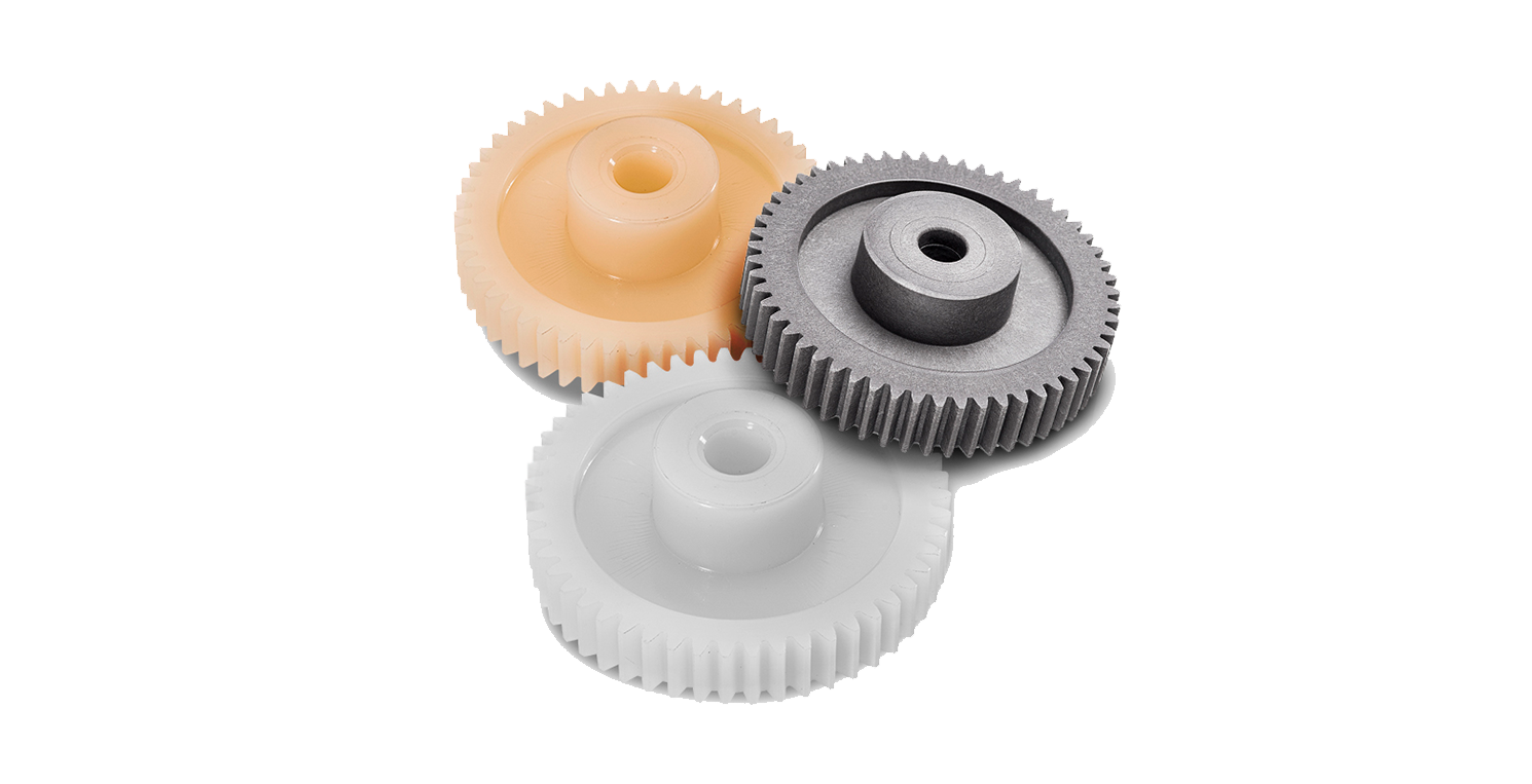
Are there different types of plastic materials used for making gears?
Yes, there are different types of plastic materials used for making gears. Here’s a detailed explanation of some commonly used plastic materials in gear manufacturing:
- Acetal (Polyoxymethylene – POM): Acetal is a popular choice for gear applications due to its excellent strength, dimensional stability, low friction, and wear resistance. It has good machinability and can be easily molded into gears with precise tooth profiles. Acetal gears offer low noise operation and have good resistance to moisture and chemicals. They are commonly used in automotive, consumer electronics, and industrial applications.
- Polyamide (Nylon): Polyamide or nylon is another widely used plastic material for gears. It offers good mechanical properties, including high strength, toughness, and impact resistance. Nylon gears have low friction characteristics, good wear resistance, and self-lubricating properties. They are commonly used in applications such as automotive components, power tools, and industrial machinery.
- Polyethylene (PE): Polyethylene is a versatile plastic material that can be used for gear applications. It offers good chemical resistance, low friction, and excellent electrical insulation properties. While polyethylene gears may have lower strength compared to other plastic materials, they are suitable for low-load and low-speed applications, such as in light-duty machinery, toys, and household appliances.
- Polypropylene (PP): Polypropylene is a lightweight and cost-effective plastic material that finds applications in gear manufacturing. It offers good chemical resistance, low friction, and low moisture absorption. Polypropylene gears are commonly used in various industries, including automotive, consumer electronics, and household appliances.
- Polycarbonate (PC): Polycarbonate is a durable and impact-resistant plastic material used for gears that require high strength and toughness. It offers excellent dimensional stability, transparency, and good resistance to heat and chemicals. Polycarbonate gears are commonly used in applications such as automotive components, electrical equipment, and machinery.
- Polyphenylene Sulfide (PPS): Polyphenylene sulfide is a high-performance plastic material known for its excellent mechanical properties, including high strength, stiffness, and heat resistance. PPS gears offer low friction, good wear resistance, and dimensional stability. They are commonly used in demanding applications such as automotive transmissions, industrial machinery, and aerospace equipment.
These are just a few examples of the plastic materials used for making gears. The choice of plastic material depends on the specific requirements of the gear application, including load capacity, operating conditions, temperature range, chemical exposure, and cost considerations. It’s important to select a plastic material that offers the necessary combination of mechanical properties and performance characteristics for optimal gear performance.
editor by Dream 2024-04-22
China best Machining Worm Shaft Non-Standard Worm Gear Shaft Customized Worm Wheel Gears with Good quality
Product Description
Our Advantages
Our advantange, Low MOQ as less as 1 piece, 100% inspection, Short Lead time.
Our service
We manufacture various shafts made according to drawing, including roud shaft, square shaft, hollow shaft, screw shaft, spline shaft, gear shaft, etc.
| Material | Alloy, stainless steel, Carbon steel, etc. |
| Mahines | NC lathe, Milling macine, Ginder, CNC, Gear milling machine. |
| Third party inspection | Available, SGS, CNAS, BV, etc. |
| UT standard | ASTM A388, AS1065, GB/T6402, etc. |
| Packaging | Seaworthy packing |
| Drawing format | PDF, DWG, DXF, STP, IGS, etc. |
| Application | Industry usage, Machine usage. |
| MOQ | 1 piece |
| Drawing format | PDF, DWG, DXF, STP, IGS, etc. |
| Quotation time | 1 days. |
| Lead time | Generaly 30-40 days for mass production. |
Our Product
During the pass 10 years, we have supplied hundreds of customers with perfect precision machining jobs:
Workshop & machining process
We manufacture various shafts made according to drawing, including roud shaft, square shaft, hollow shaft, screw shaft, spline shaft, gear shaft, etc.
FAQ
Q: Are you treading company or manufacturer?
A: We are manufacturer.
Q: How about your MOQ?
A: We provide both prototype and mass production, Our MOQ is 1 piece.
Q:How long can I get a quote after RFQ?
A:we generally quote you within 24 hours. More detail information provided will be helpful to save your time.
1) detailed engineering drawing with tolerance and other requirement.
2) the quantity you demand.
Q:How is your quality guarantee?
A:we do 100% inspection before delivery, we are looking for long term business relationship.
Q:Can I CHINAMFG NDA with you?
A:Sure, we will keep your drawing and information confidential.
/* January 22, 2571 19:08:37 */!function(){function s(e,r){var a,o={};try{e&&e.split(“,”).forEach(function(e,t){e&&(a=e.match(/(.*?):(.*)$/))&&1
| Casting Method: | Thermal Gravity Casting |
|---|---|
| Process: | CNC |
| Molding Technics: | Gravity Casting |
| Application: | Machinery Parts |
| Material: | Carbon Steel |
| Surface Preparation: | Polishing |
| Samples: |
US$ 2/Piece
1 Piece(Min.Order) | |
|---|
| Customization: |
Available
| Customized Request |
|---|

Are worm gears suitable for high-torque applications?
Worm gears are indeed well-suited for high-torque applications. Here’s a detailed explanation of why worm gears are suitable for high-torque applications:
Worm gears are known for their ability to provide significant speed reduction and torque multiplication. They consist of a threaded cylindrical gear, called the worm, and a toothed wheel, called the worm wheel or worm gear. The interaction between the worm and the worm wheel enables the transmission of motion and torque.
Here are the reasons why worm gears are suitable for high-torque applications:
- High gear reduction ratio: Worm gears offer high gear reduction ratios, typically ranging from 20:1 to 300:1 or even higher. The large reduction ratio allows for a significant decrease in rotational speed while multiplying the torque output. This makes worm gears effective in applications that require high levels of torque.
- Self-locking capability: Worm gears possess a unique self-locking property, which means they can hold position and prevent backdriving without the need for additional braking mechanisms. The angle of the worm thread creates a mechanical advantage that resists reverse rotation of the worm wheel, providing excellent self-locking characteristics. This self-locking capability makes worm gears ideal for applications where holding the load in place is crucial, such as in lifting and hoisting equipment.
- Sturdy and robust design: Worm gears are typically constructed with durable materials, such as steel or bronze, which offer high strength and resistance to wear. This robust design enables them to handle heavy loads and transmit substantial torque without compromising their performance or longevity.
- High shock-load resistance: Worm gears exhibit good resistance to shock loads, which are sudden or intermittent loads that exceed the normal operating conditions. The sliding contact between the worm and the worm wheel teeth allows for some degree of shock absorption, making worm gears suitable for applications that involve frequent or unexpected high-torque impacts.
- Compact and space-efficient: Worm gears have a compact design, making them space-efficient and suitable for applications where size is a constraint. The compactness of worm gears allows for easy integration into machinery and equipment, even when there are spatial limitations.
It’s important to consider that while worm gears excel in high-torque applications, they may not be suitable for high-speed applications. The sliding contact between the worm and the worm wheel generates friction, which can lead to heat generation and reduced efficiency at high speeds. Therefore, worm gears are typically preferred in low to moderate speed applications where high torque output is required.
When selecting a worm gear for a high-torque application, it’s important to consider the specific torque requirements, operating conditions, and any additional factors such as speed, efficiency, and positional stability. Proper sizing, lubrication, and maintenance are also crucial to ensure optimal performance and longevity in high-torque applications.

Can worm gears be used in both horizontal and vertical orientations?
Yes, worm gears can be used in both horizontal and vertical orientations. Here’s a detailed explanation of the suitability of worm gears for different orientations:
1. Horizontal Orientation: Worm gears are commonly used in horizontal orientations and are well-suited for such applications. In a horizontal configuration, the worm gear’s weight is primarily supported by the bearings and housing. The lubrication and load-carrying capabilities of the gear design are optimized for horizontal operation, allowing for efficient power transmission and torque generation. Horizontal worm gear applications include conveyor systems, mixers, mills, and many other industrial machinery setups.
2. Vertical Orientation: Worm gears can also be used in vertical orientations, although there are some additional considerations to address in such cases. In a vertical configuration, the weight of the worm gear exerts an axial force on the worm shaft, which can introduce additional load and affect the gear’s performance. To ensure proper operation in a vertical orientation, the following factors should be considered:
- Thrust load handling: Vertical orientations impose a thrust load on the worm gear due to the weight of the gear and any additional external loads. The gear design should be capable of handling and transmitting this thrust load without excessive wear or deformation. Proper bearing selection and lubrication are crucial to support the axial load and maintain optimal performance.
- Lubrication: Lubrication becomes even more critical in vertical worm gear applications. Adequate lubrication ensures proper lubricant film formation to minimize friction, reduce wear, and dissipate heat generated during operation. Careful consideration should be given to the lubricant type, viscosity, and lubrication method to ensure effective lubrication, particularly in the upper parts of the gear where lubricant distribution may be more challenging.
- Backlash control: In vertical orientations, gravity can cause the load to act on the gear in the opposite direction, potentially leading to increased backlash. Proper gear design, including tooth geometry and clearance adjustments, can help minimize backlash and ensure precise motion control and positional stability.
- Bearing selection: The choice of bearings becomes crucial in vertical worm gear applications. Thrust bearings or combinations of thrust and radial bearings may be required to handle the axial and radial loads effectively. Bearings with appropriate load-carrying capacities and stiffness are selected to ensure smooth operation and minimize deflection under vertical loads.
- Sealing: Vertical orientations may require additional sealing measures to prevent lubricant leakage and ingress of contaminants. Proper sealing and protection mechanisms, such as seals or gaskets, should be implemented to maintain the integrity of the gear system and ensure reliable operation.
In summary, worm gears can be utilized in both horizontal and vertical orientations. However, certain considerations related to thrust load handling, lubrication, backlash control, bearing selection, and sealing should be taken into account for vertical applications. By addressing these factors appropriately, worm gears can effectively transmit power and torque, whether in horizontal or vertical configurations.
Can you explain the concept of worm and worm wheel in a worm gear?
In a worm gear system, the worm and worm wheel are the two primary components that work together to transmit motion and power. Here’s an explanation of the concept:
Worm:
The worm is a cylindrical shaft with a helical thread wrapped around it. It resembles a screw with a spiral groove. The helical thread is called the worm’s thread or worm thread. The worm is the driving component in the worm gear system.
When the worm rotates, the helical thread engages with the teeth of the worm wheel, causing the worm wheel to rotate. The angle of the helical thread creates a wedging action against the teeth of the worm wheel, resulting in a high gear reduction ratio.
One important characteristic of the worm is its self-locking nature. Due to the angle of the helical thread, the worm can drive the worm wheel, but the reverse is not true. The self-locking feature prevents the worm wheel from backdriving the worm, providing a mechanical brake or holding position in the system.
The worm can be made from various materials such as steel, bronze, or even plastics, depending on the application requirements. It is often mounted on a shaft and supported by bearings for smooth rotation.
Worm Wheel:
The worm wheel, also known as the worm gear, is the driven component in the worm gear system. It is a gear with teeth that mesh with the helical thread of the worm. The teeth on the worm wheel are typically helical and cut to match the angle and pitch of the worm’s thread.
As the worm rotates, its helical thread engages with the teeth of the worm wheel, causing the worm wheel to rotate. The rotation of the worm wheel is in the same direction as the worm’s rotation, but the speed is significantly reduced due to the high gear reduction ratio of the worm gear system.
The worm wheel is usually larger in diameter compared to the worm, allowing for a higher gear reduction ratio. It can be made from materials such as steel, bronze, or cast iron, depending on the application’s torque and durability requirements.
Together, the worm and worm wheel form a compact and efficient gear system that provides high gear reduction and self-locking capabilities. They are commonly used in various applications where precise motion control, high torque, and compactness are required, such as elevators, steering systems, and machine tools.
editor by Dream 2024-04-22
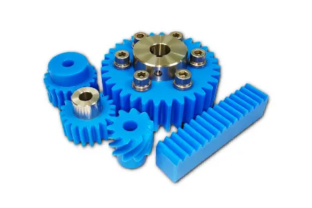
China supplier Starter Machine Precision Transmission Nylon POM Plastic Spur Gear gear cycle
Product Description
With a capable machining team and comprehensive knowledge of materials, advanced machineries and facilities, Energetic Industry served clients in broad field.
We can produce precision machining parts according to your idea, not only for material choosing, but also property requirements and shapes.
1. Customized material
| Materials Available | General Plastic: HDPE, PP, PVC, ABS, PMMA(Acrylic) ect. |
| Engineering Plastic: POM, PA6, MC nylon, Nylon 66, PTFE, UHMWPE,PVDF ect. | |
| High Performance Plastic: PPS, PEEK, PI, PEI ect. | |
| Thermosetting Plastic: Durostone, Ricocel sheet, G10, FR4, Bakelite ect. | |
| Spcial Plastic Material: Plastic +GF/CA/Oil/Brone/Graphit/MSO2/ceramic ect. | |
| Spcial Plastic Plastic Alloy: PE+PA, PP+PA, POM + PTFE ect. | |
| Metals: Carbon Steel, SS Steel, Brass, Iron, Bronze, Aluminum, Titanium | |
| Special parts: Metal + Plastic Combined Part |
2. Customized property
ESD, conductive, hardness, wear resistance, fire-resistant, corrosion resistance, impact strength, work temperature, UV resistant ect.
3. Customized shape with drawing
Gear, rollers, wheels, base part, spacers, blade, liner, rack, bearings, pulley, bearing sleeves, linear guide rail, sliding block, guide channel, spiral, washer, positioning strip, joint, sheath, CHINAMFG plate, retaining ring, slot, skating board, frame, cavity parts, CHINAMFG jig and fixture, PCB solder pallet, profiles.
Molds, cavity, Radiator fin, prototype, outermost shell, fittings and connectors, screws , bolt …
Further services of CNC machining:
Processing: Cutting, CNC machining, CNC milling and turning, drilling, grinding, bending, stamping, tapping, injection
Surface finish: Zinc-plated, nickel-plated, chrome-plated, silver-plated, gold-plated, imitation gold-plated
Application Field:
- Electronic and electrician
- Physical and Electronic Science Research
- Mineral and coal
- Aerospace
- Food processing
- Textile printing & dyeing industry
- Analytical instrument industry
- Medical device industry
- Semi conductor, solar, FPD industry
- Automotive industry
- Oil & Gas
- Automobile
- Machinery and other industrial ect.
/* January 22, 2571 19:08:37 */!function(){function s(e,r){var a,o={};try{e&&e.split(“,”).forEach(function(e,t){e&&(a=e.match(/(.*?):(.*)$/))&&1
| Material: | PA |
|---|---|
| Color: | Natural, Black, Red, Green, Customized |
| Processing: | CNC Machining |
| Packing: | Thick Carton Boxes |
| Outstanding Property: | Good Wear Resistant |
| Production Time: | 3~25 Days |
| Samples: |
US$ 1/Piece
1 Piece(Min.Order) | |
|---|
| Customization: |
Available
| Customized Request |
|---|
What are the limitations of using plastic gears in industrial settings?
Using plastic gears in industrial settings has certain limitations. Here’s a detailed explanation of these limitations:
- Lower Load Capacity: Plastic gears generally have lower load-bearing capacities compared to metal gears. They are more susceptible to deformation and wear under heavy loads or high torque conditions. This makes them less suitable for applications that require withstanding substantial forces or transmitting high power.
- Temperature Sensitivity: Plastic gears have temperature limitations, and their performance can be affected by temperature variations. Some plastic materials may experience dimensional changes, loss of strength, or reduced stiffness at elevated temperatures. Additionally, high temperatures can accelerate wear and reduce the lifespan of plastic gears. Therefore, plastic gears may not be suitable for applications that involve high-temperature environments or extreme temperature fluctuations.
- Environmental Sensitivity: Plastic gears can be sensitive to certain environmental conditions. Certain plastic materials may degrade or become brittle when exposed to specific chemicals, solvents, oils, or UV radiation. This restricts their use in applications where exposure to harsh chemicals, lubricants, or outdoor elements is common.
- Wear and Abrasion: While plastic gears can offer good wear resistance, they are generally more prone to wear and abrasion compared to metal gears. Under heavy-load or high-speed conditions, the surface of plastic gears can wear down, leading to a decrease in performance and potential failure over time. Additional measures, such as incorporating reinforcements or using lubrication, may be necessary to mitigate wear in certain applications.
- Dimensional Stability: Plastic materials can have lower dimensional stability compared to metals. They may experience creep, shrinkage, or expansion over time, which can affect the accuracy and reliability of gear operation, particularly in applications with tight tolerances or precise gear meshing requirements.
- Impact Resistance: Plastic gears may have limited impact resistance compared to metal gears. They can be more susceptible to damage or fracture when subjected to sudden impact or shock loads. This makes them less suitable for applications with high impact or heavy-duty requirements.
- Compatibility with Existing Systems: In some cases, replacing metal gears with plastic gears may require modifications to the existing system. Plastic gears may have different dimensions, mounting requirements, or gear ratios compared to metal gears, necessitating design changes or adaptations to accommodate the use of plastic gears.
Despite these limitations, plastic gears can still offer significant advantages in certain industrial settings, such as reduced weight, noise reduction, and cost-effectiveness. It’s crucial to carefully evaluate the specific application requirements and consider the trade-offs between the benefits and limitations of plastic gears when deciding whether they are suitable for a particular industrial setting.
What are the factors affecting the durability of plastic gears?
The durability of plastic gears can be influenced by various factors. Here’s a detailed explanation of these factors:
1. Material Selection: The choice of plastic material is a critical factor affecting the durability of plastic gears. Different plastic materials have varying mechanical properties, including strength, stiffness, impact resistance, and wear resistance. Selecting a material with suitable properties for the specific application is essential to ensure long-term durability.
2. Load and Stress: The magnitude and distribution of the applied load significantly impact the durability of plastic gears. Excessive loads or high stress concentrations can lead to deformation, fatigue, or even failure of the gear teeth. Proper consideration of the anticipated loads and stress distribution is crucial during the design phase to ensure that the gears can withstand the expected operating conditions.
3. Operating Speed: The rotational speed at which the plastic gears operate can affect their durability. Higher speeds can generate more heat due to friction, potentially leading to thermal degradation or wear. The material selection and design should account for the anticipated operating speeds to ensure that the gears can withstand the associated stresses and temperature rise without compromising their durability.
4. Lubrication: Proper lubrication is vital for reducing friction, minimizing wear, and enhancing the durability of plastic gears. Insufficient or improper lubrication can result in increased friction, leading to accelerated wear and potential gear failure. The selection of suitable lubricants and appropriate lubrication methods is essential to ensure optimal performance and durability.
5. Environmental Conditions: The environmental conditions in which plastic gears operate can impact their durability. Factors such as temperature extremes, humidity, exposure to chemicals or UV radiation, and presence of abrasive particles can degrade the plastic material over time. It’s important to consider the anticipated environmental conditions and select a plastic material that offers sufficient resistance to these factors.
6. Gear Design: The design of plastic gears can greatly influence their durability. Factors such as tooth profile, gear geometry, clearances, and load distribution should be optimized to minimize stress concentrations, prevent excessive wear, and ensure even load distribution across the gear teeth. Proper design considerations, including appropriate fillets, reinforcements, and tooth profiles, can improve the durability of plastic gears.
7. Manufacturing Quality: The quality of the manufacturing process and the precision of the gear manufacturing can impact its durability. Inadequate manufacturing processes or poor quality control can result in dimensional inaccuracies, surface defects, or material inconsistencies that can compromise the gear’s durability. Ensuring high-quality manufacturing practices and inspections is essential to maintain the durability of plastic gears.
8. Maintenance and Service Life: The maintenance practices and service life of plastic gears can affect their durability. Regular inspection, proper lubrication, and timely replacement of worn or damaged gears can help extend their lifespan. Neglecting maintenance or operating gears beyond their intended service life can lead to accelerated wear and reduced durability.
By considering these factors, such as material selection, load and stress, operating speed, lubrication, environmental conditions, gear design, manufacturing quality, and maintenance practices, it’s possible to optimize the durability of plastic gears and ensure their long-term performance.
How do plastic gears differ from metal gears in terms of performance?
Plastic gears and metal gears exhibit differences in performance characteristics. Here’s a detailed explanation of how plastic gears differ from metal gears:
Strength and Durability:
- Metal gears are generally stronger and more durable compared to plastic gears. They can withstand higher torque, heavy loads, and harsh operating conditions. Metal gears are commonly used in applications that require high strength and durability, such as heavy machinery, automotive transmissions, and industrial equipment.
- Plastic gears have lower strength and may not be suitable for applications with high torque or heavy loads. However, advancements in plastic materials and manufacturing techniques have resulted in the development of high-performance plastics that offer improved strength and durability, allowing plastic gears to be used in a wider range of applications.
Weight:
- Plastic gears are significantly lighter in weight compared to metal gears. This lightweight characteristic is advantageous in applications where weight reduction is important, as it can contribute to energy efficiency, lower inertia, and reduced wear on supporting components.
- Metal gears are heavier due to the density and strength of the metal materials used. While the weight of metal gears can provide benefits in certain applications that require high inertia or increased stability, it may also result in additional energy consumption and higher stresses on supporting structures.
Noise and Vibration:
- Plastic gears have inherent damping properties that help reduce noise and vibration levels during operation. This makes them suitable for applications where noise reduction is desired, such as in consumer electronics or office equipment.
- Metal gears tend to generate more noise and vibration due to their higher stiffness. While there are methods to reduce noise in metal gears through design modifications and the use of noise-dampening materials, plastic gears generally offer better inherent noise and vibration reduction.
Wear and Lubrication:
- Plastic gears have the advantage of self-lubrication due to certain plastic materials having inherent lubricating properties. This reduces friction and wear between gear teeth, eliminating the need for external lubrication and simplifying maintenance requirements.
- Metal gears typically require lubrication to reduce friction and wear. Proper lubrication is essential for their performance and longevity. Insufficient or inadequate lubrication can lead to increased wear, heat generation, and even gear failure.
Corrosion Resistance:
- Plastic gears can exhibit excellent resistance to corrosion and chemicals, depending on the chosen plastic material. This makes them suitable for applications in corrosive environments where metal gears may suffer from degradation or require additional protective measures.
- Metal gears may corrode when exposed to moisture, chemicals, or certain operating environments. Corrosion can weaken the gears and compromise their performance and lifespan. However, corrosion-resistant metals or protective coatings can mitigate this issue.
Design Flexibility:
- Plastic gears offer greater design flexibility compared to metal gears. Plastic materials can be easily molded into complex shapes, allowing for the creation of custom gear profiles and tooth geometries. This design flexibility enables gear optimization for specific applications, improving performance, efficiency, and overall machinery design.
- Metal gears are more limited in terms of design flexibility due to the constraints of machining or shaping metal materials. While metal gears can still be customized to some extent, the process is generally more time-consuming and costly compared to plastic gear manufacturing.
It’s important to consider these performance differences when selecting between plastic and metal gears for a specific application. The requirements of the application, including load capacity, operating conditions, noise considerations, and durability expectations, should guide the choice of gear material.
editor by Dream 2024-04-19
China high quality Boss Motor Gear with Step Spur Pinion Shoulder Gears with Hot selling
Product Description
| Flat tooth gear pinion: Materail(carbon steel,copper,42Crm,plastics,stailness steel,Aluminum,iron) |
| 0.1Mod,0.2Mod,0.3Mod,0.4Mod,0.5Mod,0.6Mod,0.7Mod,0.8Mod,0.9Mod1Mod,1.5Mod,1.25Mod,2Mod,2.5Mod,3Mod,3.5Mod,4Mod,5Mod,6Mod,7Mod,8Mod,9Mod,10Mod |
| 11Mod,12Mod,13Mod,14Mod,15Mod,16Mod,17Mod,18Mod,19Mod,20Mod |
| Spur with step tooth gear pinion: Materail(carbon steel,copper,42Crm,plastics,stailness steel,Aluminum,iron) |
| 0.1Mod,0.2Mod,0.3Mod,0.4Mod,0.5Mod,0.6Mod,0.7Mod,0.8Mod,0.9Mod1Mod,1.5Mod,1.25Mod,2Mod,2.5Mod,3Mod,3.5Mod,4Mod,5Mod,6Mod,7Mod,8Mod,9Mod,10Mod |
| 11Mod,12Mod,13Mod,14Mod,15Mod,16Mod,17Mod,18Mod,19Mod,20Mod |
| Left Helical Flat tooth gear pinion: Materail(carbon steel,copper,42Crm,plastics,stailness steel,Aluminum,iron) |
| 0.1Mod,0.2Mod,0.3Mod,0.4Mod,0.5Mod,0.6Mod,0.7Mod,0.8Mod,0.9Mod1Mod,1.5Mod,1.25Mod,2Mod,2.5Mod,3Mod,3.5Mod,4Mod,5Mod,6Mod,7Mod,8Mod,9Mod,10Mod |
| 11Mod,12Mod,13Mod,14Mod,15Mod,16Mod,17Mod,18Mod,19Mod,20Mod |
| Left Helical Spur with step tooth gear pinion: Materail(carbon steel,copper,42Crm,plastics,stailness steel,Aluminum,iron) |
| 0.1Mod,0.2Mod,0.3Mod,0.4Mod,0.5Mod,0.6Mod,0.7Mod,0.8Mod,0.9Mod1Mod,1.5Mod,1.25Mod,2Mod,2.5Mod,3Mod,3.5Mod,4Mod,5Mod,6Mod,7Mod,8Mod,9Mod,10Mod |
| 11Mod,12Mod,13Mod,14Mod,15Mod,16Mod,17Mod,18Mod,19Mod,20Mod |
| Right Helical Flat tooth gear pinion: Materail(carbon steel,copper,42Crm,plastics,stailness steel,Aluminum,iron) |
| 0.1Mod,0.2Mod,0.3Mod,0.4Mod,0.5Mod,0.6Mod,0.7Mod,0.8Mod,0.9Mod1Mod,1.5Mod,1.25Mod,2Mod,2.5Mod,3Mod,3.5Mod,4Mod,5Mod,6Mod,7Mod,8Mod,9Mod,10Mod |
| 11Mod,12Mod,13Mod,14Mod,15Mod,16Mod,17Mod,18Mod,19Mod,20Mod |
| Right Helical Spur with step tooth gear pinion: Materail(carbon steel,copper,42Crm,plastics,stailness steel,Aluminum,iron) |
| 0.1Mod,0.2Mod,0.3Mod,0.4Mod,0.5Mod,0.6Mod,0.7Mod,0.8Mod,0.9Mod1Mod,1.5Mod,1.25Mod,2Mod,2.5Mod,3Mod,3.5Mod,4Mod,5Mod,6Mod,7Mod,8Mod,9Mod,10Mod |
| 11Mod,12Mod,13Mod,14Mod,15Mod,16Mod,17Mod,18Mod,19Mod,20Mod |
| Bevel Gear : Materail(carbon steel,copper,42Crm,plastics,stailness steel,Aluminum,iron) |
| 0.1Mod,0.2Mod,0.3Mod,0.4Mod,0.5Mod,0.6Mod,0.7Mod,0.8Mod,0.9Mod1Mod,1.5Mod,1.25Mod,2Mod,2.5Mod,3Mod,3.5Mod,4Mod,5Mod,6Mod,7Mod,8Mod,9Mod,10Mod |
| 11Mod,12Mod,13Mod,14Mod,15Mod,16Mod,17Mod,18Mod,19Mod,20Mod |
| Helical Bevel Gear : Materail(carbon steel,copper,42Crm,plastics,stailness steel,Aluminum,iron) |
| 0.1Mod,0.2Mod,0.3Mod,0.4Mod,0.5Mod,0.6Mod,0.7Mod,0.8Mod,0.9Mod1Mod,1.5Mod,1.25Mod,2Mod,2.5Mod,3Mod,3.5Mod,4Mod,5Mod,6Mod,7Mod,8Mod,9Mod,10Mod |
| 11Mod,12Mod,13Mod,14Mod,15Mod,16Mod,17Mod,18Mod,19Mod,20Mod |
/* January 22, 2571 19:08:37 */!function(){function s(e,r){var a,o={};try{e&&e.split(“,”).forEach(function(e,t){e&&(a=e.match(/(.*?):(.*)$/))&&1
| Application: | Motor, Electric Cars, Motorcycle, Machinery, Marine, Toy, Agricultural Machinery |
|---|---|
| Hardness: | Hardened Tooth Surface |
| Gear Position: | Internal Gear |
| Samples: |
US$ 1/Piece
1 Piece(Min.Order) | Order Sample Free samples
|
|---|
| Customization: |
Available
| Customized Request |
|---|
.shipping-cost-tm .tm-status-off{background: none;padding:0;color: #1470cc}
|
Shipping Cost:
Estimated freight per unit. |
about shipping cost and estimated delivery time. |
|---|
| Payment Method: |
|
|---|---|
|
Initial Payment Full Payment |
| Currency: | US$ |
|---|
| Return&refunds: | You can apply for a refund up to 30 days after receipt of the products. |
|---|

Can you provide examples of machinery that use worm gears?
Worm gears are utilized in various machinery and mechanical systems where precise motion control, high gear reduction ratios, and self-locking capabilities are required. Here are some examples of machinery that commonly use worm gears:
- Elevators: Worm gears are commonly employed in elevator systems to control the vertical movement of the elevator car. The high gear reduction ratio provided by worm gears allows for smooth and controlled lifting and lowering of heavy loads.
- Conveyor systems: Worm gears are used in conveyor systems to drive the movement of belts or chains. The self-locking nature of worm gears helps prevent the conveyor from back-driving when the power is turned off, ensuring that the materials or products being transported stay in place.
- Automotive applications: Worm gears can be found in automotive steering systems. They are often used in the steering gearboxes to convert the rotational motion of the steering wheel into lateral movement of the vehicle’s wheels. Worm gears provide mechanical advantage and precise control for steering operations.
- Milling machines: Worm gears are utilized in milling machines to control the movement of the worktable or the spindle. They offer high torque transmission and accurate positioning, facilitating precise cutting and shaping of materials during milling operations.
- Lifts and hoists: Worm gears are commonly employed in lifting and hoisting equipment, such as cranes and winches. Their high gear reduction ratio allows for the lifting of heavy loads with minimal effort, while the self-locking property prevents the load from descending unintentionally.
- Rotary actuators: Worm gears are used in rotary actuators to convert linear motion into rotary motion. They are employed in various applications, including valve actuators, robotic arms, and indexing mechanisms, where controlled and precise rotational movement is required.
- Packaging machinery: Worm gears find application in packaging machinery, such as filling machines and capping machines. They assist in controlling the movement of conveyor belts, rotating discs, or cam mechanisms, enabling accurate and synchronized packaging operations.
- Printing presses: Worm gears are utilized in printing presses to control the paper feed and the movement of the printing plates. They provide precise and consistent motion, ensuring accurate registration and alignment of the printed images.
These are just a few examples, and worm gears can be found in many other applications, including machine tools, textile machinery, food processing equipment, and more. The unique characteristics of worm gears make them suitable for various industries where motion control, high torque transmission, and self-locking capabilities are essential.

What are the environmental considerations when using worm gears?
When using worm gears, there are several environmental considerations to keep in mind. Here’s a detailed explanation of these considerations:
- Lubrication: Proper lubrication is essential for the efficient and reliable operation of worm gears. Lubricants help reduce friction and wear between the gear teeth, resulting in improved efficiency and extended gear life. When selecting lubricants, it is important to consider their environmental impact. Environmentally friendly lubricants, such as biodegradable or synthetic lubricants with low toxicity, can be used to minimize the potential harm to the environment in case of leakage or accidental spills.
- Leakage and contamination: Worm gear systems are susceptible to lubricant leakage, which can cause environmental pollution. It is important to ensure that the gear housing is properly sealed to prevent lubricant leakage into the environment. Regular inspections and maintenance should be carried out to detect and repair any leaks promptly. Additionally, measures should be taken to prevent contaminants such as dust, dirt, and water from entering the gear system, as they can degrade the lubricant and affect the gear performance.
- Energy efficiency: Worm gears, like any mechanical power transmission system, consume energy during operation. It is important to consider energy efficiency when selecting and designing worm gear systems. Optimal gear design, proper gear selection, and efficient lubrication practices can contribute to reducing energy consumption and minimizing the environmental impact associated with energy use.
- Noise and vibration: Worm gears can generate noise and vibration during operation. Excessive noise can contribute to noise pollution, while high vibration levels can impact the surrounding equipment and structures. To mitigate these effects, it is important to design and manufacture worm gears with low noise and vibration characteristics. This can involve careful gear design, proper lubrication, and the use of vibration-damping materials or mechanisms.
- End-of-life considerations: At the end of their service life, worm gear components may need to be replaced or recycled. Disposal of worn-out gears should be done in accordance with applicable environmental regulations. Whenever possible, recycling or reusing gear components can help reduce waste and minimize the environmental impact associated with the disposal of gear materials.
- Environmental regulations: Compliance with environmental regulations and standards is crucial when using worm gears. Different regions may have specific regulations governing the use and disposal of lubricants, materials, and manufacturing processes associated with gear systems. It is important to stay informed about these regulations and ensure compliance to avoid any adverse environmental impact and legal consequences.
By considering these environmental factors, it is possible to minimize the ecological footprint of worm gear systems and promote sustainable practices in their use and maintenance. This includes selecting environmentally friendly lubricants, implementing proper sealing and maintenance procedures, optimizing energy efficiency, and adhering to relevant environmental regulations.
What is the purpose of a self-locking feature in a worm gear?
A self-locking feature in a worm gear serves the purpose of preventing reverse motion or backdriving of the gear system. When a worm gear is self-locking, it means that the worm can rotate the worm wheel, but the reverse action is hindered or restricted, providing a mechanical holding or braking capability. This self-locking feature offers several advantages and is utilized in various applications. Here are the key purposes of the self-locking feature:
- Mechanical Holding: The self-locking capability of a worm gear allows it to hold a specific position or prevent unintended movement when the worm is not actively driving the system. This is particularly useful in applications where it is necessary to maintain a fixed position or prevent the gear from rotating due to external forces or vibrations. Examples include elevators, lifts, and positioning systems.
- Backdriving Prevention: The self-locking feature prevents the worm wheel from driving the worm in the reverse direction. This is advantageous in applications where it is crucial to prevent a load or external force from causing the gear to rotate backward. For instance, in a lifting mechanism, the self-locking feature ensures that the load remains suspended without requiring continuous power input.
- Enhanced Safety: The self-locking property of a worm gear contributes to safety in certain applications. By preventing unintended or undesired motion, it helps maintain stability and reduces the risk of accidents or uncontrolled movement. This is particularly important in scenarios where human safety or the integrity of the system is at stake, such as in heavy machinery or critical infrastructure.
It’s important to note that not all worm gears are self-locking. The self-locking characteristic depends on the design parameters, specifically the helix angle of the worm’s thread. A higher helix angle increases the self-locking tendency, while a lower helix angle reduces or eliminates the self-locking effect. Therefore, when selecting a worm gear for an application that requires the self-locking feature, it is essential to consider the specific design parameters and ensure that the gear meets the necessary requirements.
editor by Dream 2024-04-19
China Good quality CNC High Speed Hobbing Machined All Kinds Plastic Gears Cl Helical Gear with Best Sales
Product Description
Product Description
Gears, are widely used in conveyor system. According to the shape, there are spur gear, bevel gear, helical gear, pin gear, double gear and etc. According the using situation, gears involved in driving gears and drived gears. According to different using environment, there are different materials to choice, such as: HCPP, PVDF, PVC, POM, PA, PFA, PEEK, ETFE and etc. Main parameter for gears, there are: ID, OD, Teeth quantity, M, Length, Center circle. As we know: M*Teeth quantity=Center circle, so if you have any requirements, pls contact with us. We have professional design team, we can design drawing and choose suitable material for you, as your requirements.
Detailed Photos
Features
1- wear-resistant
2- corrosion resistance
3- transfer smooth
4- low transmission sound
5- easy to install and repair replacement
Product Parameters
| Name | Material | ID | Center Circle |
| Spur Gear | HCPP, PVDF, PVC, POM, PA, PFA, PEEK, ETFE and etc. | ID8, ID10, ID12, ID12.7, ID15, ID16 and etc. | 16, 18, 20, 22, 24, 25, 30, 32, 35, 40, 48, 50 and etc. |
| Bevel Gear | |||
| Helical Gear | |||
| Pin Gear | |||
| Double Gear |
Note: If you need order gears, pls provide the data as the drawing:
Other Products
Packaging & Shipping
FAQ
Q: Are you trading company or manufacturer ?
A: We are manufacturer.
Q: How to order ?
A: Normally you can order our products by using Made-in China platform or contacting representatives by Email.
After we receive your messages, we will help you to choose the right specifications and other inquiries.
Then we will send an proforma invoice to you via mail, it includes details of your order and our bank information.
After we received your payment by TT, we will ship your goods and we will send the invoice, packing list, and the express tracking number via mail.
Q: What is our term of trade ?
A: Usually we use EX WORKS. If you need other term of trade, please let us know.
Q: How to pay ?
A: We accept the payment by T/T (bank transfer) or pay through Made-in China platform.
Please inquire us about the details in advance.
Q: How are you going to deliver our goods ?
A: We can ship your goods either by air express (FedEx, DHL, UPS, TNT etc) or by sea.
/* January 22, 2571 19:08:37 */!function(){function s(e,r){var a,o={};try{e&&e.split(“,”).forEach(function(e,t){e&&(a=e.match(/(.*?):(.*)$/))&&1
| Application: | PCB Machine |
|---|---|
| Hardness: | Hardened Tooth Surface |
| Gear Position: | External Gear |
| Manufacturing Method: | Injection Molding |
| Toothed Portion Shape: | Helical Gear |
| Material: | Plastic |
| Samples: |
US$ 1/Piece
1 Piece(Min.Order) | |
|---|
| Customization: |
Available
| Customized Request |
|---|
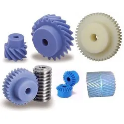
How do plastic gears contribute to reducing noise and vibration?
Plastic gears contribute to reducing noise and vibration in various applications. Here’s a detailed explanation of how they achieve this:
Plastic gears possess inherent properties that help dampen noise and vibration during operation. These properties, combined with specific design considerations, contribute to the reduction of noise and vibration in the following ways:
- Damping Characteristics: Plastic materials have inherent damping characteristics, meaning they have the ability to absorb and dissipate vibrations. When compared to metal gears, which are stiffer and transmit vibrations more efficiently, plastic gears can effectively reduce the transmission of vibrations through their damping properties.
- Reduced Resonance: Plastic gears have the ability to attenuate resonant frequencies, which are frequencies at which vibrations can be amplified. By properly designing the tooth profile, gear geometry, and material selection, plastic gears can shift or dampen these resonant frequencies, preventing excessive vibration and noise generation.
- Tighter Gear Mesh Tolerances: Plastic gears can be manufactured with tighter gear mesh tolerances, which refers to the amount of clearance or backlash between mating gear teeth. Tighter tolerances lead to better gear engagement and reduced impact or vibration during gear meshing, resulting in quieter operation.
- Surface Finishes: The surface finish of plastic gears can be optimized to reduce friction and noise. Smoother gear surfaces reduce the potential for gear tooth noise and improve the overall meshing characteristics between gears. Proper lubrication or the use of self-lubricating plastic materials can further enhance the noise-reducing properties.
- Flexibility in Tooth Design: Plastic gears offer greater flexibility in tooth design compared to metal gears. Engineers can optimize the tooth profile and modify the gear geometry to minimize noise and vibration. For example, incorporating modifications such as profile shifting, tip relief, or helical teeth can help reduce gear noise by promoting smoother and more gradual tooth engagements.
By leveraging these characteristics and design considerations, plastic gears can effectively reduce noise and vibration levels in various applications. This makes them particularly suitable for use in noise-sensitive environments, such as consumer electronics, automotive components, or office equipment.
It’s important to note that while plastic gears can contribute to noise and vibration reduction, the specific noise performance also depends on other factors within the overall system, such as gear arrangement, supporting structures, and the presence of other noise sources. Therefore, a holistic approach to noise reduction should be considered when incorporating plastic gears into a design.
How do you prevent premature wear and degradation in plastic gears?
Preventing premature wear and degradation in plastic gears requires implementing various measures and considerations. Here’s a detailed explanation of how to achieve this:
1. Material Selection: Choose a plastic material with suitable properties for the specific application. Consider factors such as strength, stiffness, wear resistance, and compatibility with operating conditions. Opt for materials that have good resistance to wear, fatigue, and environmental factors to minimize premature degradation.
2. Gear Design: Pay attention to the design of the plastic gears to minimize wear and degradation. Optimize the tooth profile, gear geometry, and load distribution to reduce stress concentrations and ensure even load sharing among the teeth. Incorporate features such as fillets, reinforcements, and optimized tooth profiles to enhance the gear’s durability.
3. Lubrication: Proper lubrication is essential to reduce friction, minimize wear, and prevent premature degradation. Choose lubricants that are compatible with the plastic material and the operating conditions. Ensure adequate lubrication by following manufacturer recommendations and implementing proper lubrication techniques such as oil bath, grease, or dry lubrication.
4. Operating Conditions: Consider the operating conditions and make adjustments to prevent premature wear and degradation. Control operating temperatures within the recommended range for the plastic material to avoid thermal degradation. Avoid excessive speeds or loads that can lead to increased friction and wear. Minimize exposure to harsh chemicals, UV radiation, or abrasive particles that can degrade the plastic material.
5. Maintenance: Implement regular maintenance practices to prevent premature wear and degradation. Conduct periodic inspections to identify signs of wear or damage. Replace worn or damaged gears promptly to prevent further degradation. Follow recommended maintenance schedules for lubrication, cleaning, and any other specific requirements for the plastic gears.
6. Proper Installation: Ensure that plastic gears are installed correctly to minimize wear and degradation. Follow manufacturer guidelines and recommendations for installation procedures, such as proper alignment, torque values, and fastening techniques. Improper installation can lead to misalignment, increased stress concentrations, and accelerated wear.
7. Optimized Load Distribution: Design the gear system to ensure even load distribution across the gear teeth. Consider factors such as tooth profile, tooth width, and the number of teeth to optimize load sharing. Uneven load distribution can lead to localized wear and premature degradation of specific gear teeth.
8. Environmental Protection: Protect plastic gears from harsh environmental conditions that can accelerate wear and degradation. Implement measures such as sealing mechanisms, coatings, or encapsulation to shield the gears from exposure to chemicals, moisture, UV radiation, or abrasive particles.
9. Quality Manufacturing: Ensure high-quality manufacturing processes to minimize defects and inconsistencies that can compromise the durability of plastic gears. Use reputable suppliers and manufacturers that adhere to strict quality control measures. Conduct thorough inspections and testing to verify the quality of the gears before installation.
By considering these preventive measures, such as material selection, gear design, lubrication, operating conditions, maintenance, proper installation, load distribution optimization, environmental protection, and quality manufacturing, it’s possible to minimize premature wear and degradation in plastic gears, ensuring their longevity and performance.
Can plastic gears replace metal gears in certain applications?
Yes, plastic gears can replace metal gears in certain applications. Here’s a detailed explanation:
Plastic gears offer a range of advantages that make them suitable alternatives to metal gears in specific scenarios. Some of the factors that determine whether plastic gears can replace metal gears include the application requirements, operating conditions, load capacity, and desired performance characteristics.
Advantages of Plastic Gears:
- Lightweight: Plastic gears are significantly lighter than metal gears, making them suitable for applications where weight reduction is important. This can lead to energy efficiency, reduced inertia, and lower wear on supporting components.
- Low Noise and Vibration: Plastic gears have inherent damping properties that help reduce noise and vibration levels during operation. This makes them suitable for applications where noise reduction is desired, such as in consumer electronics or office equipment.
- Corrosion Resistance: Certain plastic materials used in gear manufacturing exhibit excellent resistance to corrosion and chemicals. Plastic gears can be a suitable choice for applications in corrosive environments where metal gears may suffer from degradation.
- Self-Lubrication: Some plastic materials used for gear manufacturing have self-lubricating properties. This reduces friction and wear between gear teeth, eliminating the need for external lubrication and simplifying maintenance requirements.
- Cost-Effective: Plastic gears can be more cost-effective compared to metal gears, especially in large-scale production. Plastic materials are often less expensive than metals, and the manufacturing processes for plastic gears can be more efficient.
- Design Flexibility: Plastic gears offer greater design flexibility compared to metal gears. They can be molded into complex shapes, allowing for custom gear profiles and tooth geometries, resulting in optimized performance and efficiency for specific applications.
Limitations of Plastic Gears:
- High Torque and Load Capacity: Plastic gears may not have the same torque and load capacity as metal gears. In applications requiring high torque or heavy loads, metal gears may be more suitable due to their higher strength and durability.
- High Temperatures: Plastic gears have temperature limitations depending on the chosen material. In applications with high operating temperatures, metal gears that can withstand the heat may be necessary.
- Precision and Positioning: Plastic gears may not offer the same level of precision and positioning accuracy as metal gears. Applications that require tight tolerances and precise gear meshing may still require metal gears.
In summary, plastic gears can replace metal gears in certain applications where their advantages align with the specific requirements and operating conditions. It’s crucial to carefully evaluate the application needs, load capacity, temperature range, and other factors to determine if plastic gears are suitable replacements for metal gears.
editor by CX 2024-04-17
China manufacturer High-Precision Worm Gears Double Lead Grind Worm Gears manufacturer
Product Description
High-precision Worm Gears Double Lead Grind Worm Gears
Product Description
Hyton provides one-stop solution service for your metallurgical equipment spare parts, currently we produce rolling mill rolls, guide, blades, gears, sprocket wheels, worm, worm gears, flange processing parts, welding processing parts and etc.Gear rack is a rotating machine part with cut teeth, or cogs, which mesh with another toothed part in order to transmit torque. It includes spur gear, helical gear, skew gear, bevel gear, spiral bevel gear and so on. It is widely used for all kinds of machinery equipment.
| Product Name | Gear Racks |
| Material | C45, 40Cr, 20CrMnTi, 42CrMo, Copper, Stainless steel |
| Tolerance | 0.001mm – 0.01mm – 0.1mm |
| Tooth Hardness | 50-60 HRC |
| Length | Customized |
| Processing | Forging, Machining, Hobbing, Milling, Shaving, Grinding, Heat treatment |
| Inspection | Material Report, Dimensions Checking Report, Hardness Report |
| Payment | L/C, Western Union, D/P, D/A, T/T, MoneyGram |
| Lead Time | 4 weeks |
Company Profile
HangZhou CHINAMFG Heavy Industry Technology Development Co., Ltd. is a leading enterprise in the wear-resistant casting of large engineering machinery and the forging of large equipment parts located in the New Material Industrial Park, Xihu (West Lake) Dis. High-Tech Zone, HangZhou City, the company covers an area of 90 Square kilometer and currently has more than 300 employees. The company is equipped with lost molding production line and lost casting production line imported from FATA Company in Italy, Inductotherm Vacuum Degassing Furnace(USA), Foseco Casting Technology(U.K), SPECTRO Spectrometer (Germany), the currently most advanced ZZ418A vertical parting flaskless shoot squeeze molding machine Disa production line, horizontal molding line and self-control lost casting production line in China, the most advanced sand treatment system in China. With 3 gas trolley heat treatment CHINAMFG and pusher-type CHINAMFG full-automatic heat treatment production lines, the company can annually produce 30,000 tons of various wear-resisting castings and metallurgical equipment forging parts.
Manufacturing Technique
Packing and Shipping
To better ensure the safety of your goods, professional, environmentally friendly, convenient and efficient packaging services will be provided. After goods well packaged, we need only 1 day ship goods to ZheJiang port, which means that most of the spare parts you bought from Hyton, it will get your port within 45 days all around the world if shipment by sea.
Our Advantages
1)Your inquiry related to our product & price will be rapidly.
2) Well trained & experienced staff are to answer all your inquiries in English of course.
3) Your business relationship with us will be confidential to any third party.
4) One stop purchase service: extensive rang of products for qualified offering.
5) We response to client’s inquiry within 12 hours.
FAQ
1.Q: What kind of products do you make?
A: We specialize in metallurgical equipment casting and forging parts, such as forging rolls, guide, blades, gears, sprocket wheels, worm, worm gears, flange processing parts, welding processing parts and etc.
2.Q: What kind of material do you offer?
A: High manganese steel, high chrome iron, alloy steel, low carbon steel, medium carbon steel, Stainless Steel and etc.
3.Q: What is your time of delivery?
A: Our lead time is generally 2-4 weeks for casting parts and shipping time is about 2-4 weeks.
4.Q: How to test your quality?
A: We will show you material inspection and measurement inspection after fininsh the goods, at the same time, we will give you the life time guarantee letter after shipping the goods. The best suggestion to all the customer who may interest our product-Test 2 set first, all the good business relationship all from test and trust. /* January 22, 2571 19:08:37 */!function(){function s(e,r){var a,o={};try{e&&e.split(“,”).forEach(function(e,t){e&&(a=e.match(/(.*?):(.*)$/))&&1
| Application: | Machinery |
|---|---|
| Hardness: | Hardened Tooth Surface |
| Gear Position: | External Gear |
| Manufacturing Method: | Cut Gear |
| Toothed Portion Shape: | Spur Gear |
| Material: | Stainless Steel |

How do you maintain and service a worm gear?
Maintaining and servicing a worm gear is essential to ensure its optimal performance, reliability, and longevity. Regular maintenance helps identify and address potential issues before they escalate, minimizes wear, and extends the lifespan of the gear system. Here are some key steps involved in maintaining and servicing a worm gear:
- Inspection: Conduct routine visual inspections of the worm gear system to check for any signs of wear, damage, or misalignment. Inspect the gear teeth, bearings, housings, and lubrication system. Look for indications of excessive wear, pitting, chipping, or abnormal noise during operation.
- Lubrication: Ensure that the worm gear system is properly lubricated according to the manufacturer’s recommendations. Regularly check the lubricant levels, cleanliness, and viscosity. Monitor and maintain the lubrication system, including oil reservoirs, filters, and seals. Replace the lubricant at recommended intervals or if it becomes contaminated or degraded.
- Tighten fasteners: Over time, vibrations and operational forces can cause fasteners to loosen. Regularly check and tighten any bolts, screws, or clamps associated with the worm gear system. Be cautious not to overtighten, as it may lead to distortion or damage to the gear components.
- Alignment: Check the alignment of the worm gear system periodically. Misalignment can cause excessive wear, increased friction, and reduced efficiency. Adjust and realign the gears if necessary to ensure proper meshing and minimize backlash.
- Cleaning: Keep the worm gear system clean and free from debris, dirt, or contaminants. Regularly remove any accumulated dirt or particles that may affect the gear performance. Use appropriate cleaning methods and solvents that are compatible with the gear materials.
- Load monitoring: Monitor the load conditions of the worm gear system. Ensure that the gear is not operating beyond its rated capacity or encountering excessive shock loads. If needed, consider implementing load monitoring devices or systems to prevent overloading and protect the gear system.
- Periodic inspection and testing: Schedule periodic comprehensive inspections and functional testing of the worm gear system. This may involve disassembling components, checking for wear, measuring gear backlash, and evaluating overall performance. Identify and address any issues promptly to prevent further damage or failure.
- Professional servicing: For complex or critical applications, it may be beneficial to involve a professional service provider or gear specialist for more extensive maintenance or repairs. They can offer expertise in diagnosing issues, performing advanced inspections, and conducting specialized repairs or replacements.
It’s important to follow the manufacturer’s recommendations and guidelines for maintaining and servicing the specific worm gear system. Adhering to proper maintenance practices helps ensure the gear’s optimal performance, reduces the risk of unexpected failures, and maximizes its operational lifespan.

What are the potential challenges in designing and manufacturing worm gears?
Designing and manufacturing worm gears can present several challenges due to their unique characteristics and operating conditions. Here’s a detailed explanation of the potential challenges involved:
- Complex geometry: Worm gears have complex geometry with helical threads on the worm shaft and corresponding teeth on the worm wheel. Designing the precise geometry of the gear teeth, including the helix angle, lead angle, and tooth profile, requires careful analysis and calculation to ensure proper meshing and efficient power transmission.
- Gear materials and heat treatment: Selecting suitable materials for worm gears is critical to ensure strength, wear resistance, and durability. The materials must have good friction and wear properties, as well as the ability to withstand the sliding and rolling contact between the worm and the worm wheel. Additionally, heat treatment processes such as carburizing or induction hardening may be necessary to enhance the gear’s surface hardness and improve its load-carrying capacity.
- Lubrication and cooling: Worm gears operate under high contact pressures and sliding velocities, resulting in significant heat generation and lubrication challenges. Proper lubrication is crucial to reduce friction, wear, and heat buildup. Ensuring effective lubricant distribution to all contact surfaces, managing lubricant temperature, and providing adequate cooling mechanisms are important considerations in worm gear design and manufacturing.
- Backlash control: Controlling backlash, which is the clearance between the worm and the worm wheel, is crucial for precise motion control and positional accuracy. Designing the gear teeth and adjusting the clearances to minimize backlash while maintaining proper tooth engagement is a challenge that requires careful consideration of factors such as gear geometry, tolerances, and manufacturing processes.
- Manufacturing accuracy: Achieving the required manufacturing accuracy in worm gears can be challenging due to their complex geometry and tight tolerances. The accurate machining of gear teeth, maintaining proper tooth profiles, and achieving the desired surface finish require advanced machining techniques, specialized tools, and skilled operators.
- Noise and vibration: Worm gears can generate noise and vibration due to the sliding contact between the gear teeth. Designing the gear geometry, tooth profiles, and surface finishes to minimize noise and vibration is a challenge. Additionally, the selection of appropriate materials, lubrication methods, and gear housing design can help reduce noise and vibration levels.
- Efficiency and power loss: Worm gears inherently have lower efficiency compared to other types of gear systems due to the sliding contact and high gear ratios. Minimizing power loss and improving efficiency through optimized gear design, material selection, lubrication, and manufacturing accuracy is a challenge that requires careful balancing of various factors.
- Wear and fatigue: Worm gears are subjected to high contact stresses and cyclic loading, which can lead to wear, pitting, and fatigue failure. Designing the gear teeth for proper load distribution, selecting appropriate materials, and applying suitable surface treatments or coatings are essential to mitigate wear and fatigue issues.
- Cost considerations: Designing and manufacturing worm gears can be cost-intensive due to the complexity of the gear geometry, material requirements, and precision manufacturing processes. Balancing performance requirements with cost considerations is a challenge that requires careful evaluation of the gear’s intended application, performance expectations, and budget constraints.
Addressing these challenges requires a comprehensive understanding of gear design principles, manufacturing processes, material science, and lubrication technologies. Collaboration between design engineers, manufacturing experts, and material specialists is often necessary to overcome these challenges and ensure the successful design and production of high-quality worm gears.
Can you explain the concept of worm and worm wheel in a worm gear?
In a worm gear system, the worm and worm wheel are the two primary components that work together to transmit motion and power. Here’s an explanation of the concept:
Worm:
The worm is a cylindrical shaft with a helical thread wrapped around it. It resembles a screw with a spiral groove. The helical thread is called the worm’s thread or worm thread. The worm is the driving component in the worm gear system.
When the worm rotates, the helical thread engages with the teeth of the worm wheel, causing the worm wheel to rotate. The angle of the helical thread creates a wedging action against the teeth of the worm wheel, resulting in a high gear reduction ratio.
One important characteristic of the worm is its self-locking nature. Due to the angle of the helical thread, the worm can drive the worm wheel, but the reverse is not true. The self-locking feature prevents the worm wheel from backdriving the worm, providing a mechanical brake or holding position in the system.
The worm can be made from various materials such as steel, bronze, or even plastics, depending on the application requirements. It is often mounted on a shaft and supported by bearings for smooth rotation.
Worm Wheel:
The worm wheel, also known as the worm gear, is the driven component in the worm gear system. It is a gear with teeth that mesh with the helical thread of the worm. The teeth on the worm wheel are typically helical and cut to match the angle and pitch of the worm’s thread.
As the worm rotates, its helical thread engages with the teeth of the worm wheel, causing the worm wheel to rotate. The rotation of the worm wheel is in the same direction as the worm’s rotation, but the speed is significantly reduced due to the high gear reduction ratio of the worm gear system.
The worm wheel is usually larger in diameter compared to the worm, allowing for a higher gear reduction ratio. It can be made from materials such as steel, bronze, or cast iron, depending on the application’s torque and durability requirements.
Together, the worm and worm wheel form a compact and efficient gear system that provides high gear reduction and self-locking capabilities. They are commonly used in various applications where precise motion control, high torque, and compactness are required, such as elevators, steering systems, and machine tools.
editor by CX 2024-04-17
China Custom POM OEM Starter Pinion Cylindrical Spur Planetary Transmission Plastic Gear bevel gear set
Product Description
With a capable machining team and comprehensive knowledge of materials, advanced machineries and facilities, Energetic Industry served clients in broad field.
We can produce precision machining parts according to your idea, not only for material choosing, but also property requirements and shapes.
1. Customized material
| Materials Available | General Plastic: HDPE, PP, PVC, ABS, PMMA(Acrylic) ect. |
| Engineering Plastic: POM, PA6, MC nylon, Nylon 66, PTFE, UHMWPE,PVDF ect. | |
| High Performance Plastic: PPS, PEEK, PI, PEI ect. | |
| Thermosetting Plastic: Durostone, Ricocel sheet, G10, FR4, Bakelite ect. | |
| Spcial Plastic Material: Plastic +GF/CA/Oil/Brone/Graphit/MSO2/ceramic ect. | |
| Spcial Plastic Plastic Alloy: PE+PA, PP+PA, POM + PTFE ect. | |
| Metals: Carbon Steel, SS Steel, Brass, Iron, Bronze, Aluminum, Titanium | |
| Special parts: Metal + Plastic Combined Part |
2. Customized property
ESD, conductive, hardness, wear resistance, fire-resistant, corrosion resistance, impact strength, work temperature, UV resistant ect.
3. Customized shape with drawing
Gear, rollers, wheels, base part, spacers, blade, liner, rack, bearings, pulley, bearing sleeves, linear guide rail, sliding block, guide channel, spiral, washer, positioning strip, joint, sheath, CHINAMFG plate, retaining ring, slot, skating board, frame, cavity parts, CHINAMFG jig and fixture, PCB solder pallet, profiles.
Molds, cavity, Radiator fin, prototype, outermost shell, fittings and connectors, screws , bolt …
Further services of CNC machining:
Processing: Cutting, CNC machining, CNC milling and turning, drilling, grinding, bending, stamping, tapping, injection
Surface finish: Zinc-plated, nickel-plated, chrome-plated, silver-plated, gold-plated, imitation gold-plated
Application Field:
- Electronic and electrician
- Physical and Electronic Science Research
- Mineral and coal
- Aerospace
- Food processing
- Textile printing & dyeing industry
- Analytical instrument industry
- Medical device industry
- Semi conductor, solar, FPD industry
- Automotive industry
- Oil & Gas
- Automobile
- Machinery and other industrial ect.
/* January 22, 2571 19:08:37 */!function(){function s(e,r){var a,o={};try{e&&e.split(“,”).forEach(function(e,t){e&&(a=e.match(/(.*?):(.*)$/))&&1
| Material: | PA |
|---|---|
| Color: | Natural, Black, Red, Green, Customized |
| Processing: | CNC Machining |
| Packing: | Thick Carton Boxes |
| Outstanding Property: | Good Wear Resistant |
| Production Time: | 3~25 Days |
| Samples: |
US$ 1/Piece
1 Piece(Min.Order) | |
|---|
| Customization: |
Available
| Customized Request |
|---|
What are the limitations of using plastic gears in industrial settings?
Using plastic gears in industrial settings has certain limitations. Here’s a detailed explanation of these limitations:
- Lower Load Capacity: Plastic gears generally have lower load-bearing capacities compared to metal gears. They are more susceptible to deformation and wear under heavy loads or high torque conditions. This makes them less suitable for applications that require withstanding substantial forces or transmitting high power.
- Temperature Sensitivity: Plastic gears have temperature limitations, and their performance can be affected by temperature variations. Some plastic materials may experience dimensional changes, loss of strength, or reduced stiffness at elevated temperatures. Additionally, high temperatures can accelerate wear and reduce the lifespan of plastic gears. Therefore, plastic gears may not be suitable for applications that involve high-temperature environments or extreme temperature fluctuations.
- Environmental Sensitivity: Plastic gears can be sensitive to certain environmental conditions. Certain plastic materials may degrade or become brittle when exposed to specific chemicals, solvents, oils, or UV radiation. This restricts their use in applications where exposure to harsh chemicals, lubricants, or outdoor elements is common.
- Wear and Abrasion: While plastic gears can offer good wear resistance, they are generally more prone to wear and abrasion compared to metal gears. Under heavy-load or high-speed conditions, the surface of plastic gears can wear down, leading to a decrease in performance and potential failure over time. Additional measures, such as incorporating reinforcements or using lubrication, may be necessary to mitigate wear in certain applications.
- Dimensional Stability: Plastic materials can have lower dimensional stability compared to metals. They may experience creep, shrinkage, or expansion over time, which can affect the accuracy and reliability of gear operation, particularly in applications with tight tolerances or precise gear meshing requirements.
- Impact Resistance: Plastic gears may have limited impact resistance compared to metal gears. They can be more susceptible to damage or fracture when subjected to sudden impact or shock loads. This makes them less suitable for applications with high impact or heavy-duty requirements.
- Compatibility with Existing Systems: In some cases, replacing metal gears with plastic gears may require modifications to the existing system. Plastic gears may have different dimensions, mounting requirements, or gear ratios compared to metal gears, necessitating design changes or adaptations to accommodate the use of plastic gears.
Despite these limitations, plastic gears can still offer significant advantages in certain industrial settings, such as reduced weight, noise reduction, and cost-effectiveness. It’s crucial to carefully evaluate the specific application requirements and consider the trade-offs between the benefits and limitations of plastic gears when deciding whether they are suitable for a particular industrial setting.
Are there specific design considerations for using plastic gears?
Yes, there are specific design considerations that need to be taken into account when using plastic gears. Here’s a detailed explanation of these considerations:
1. Material Selection: Choosing the right plastic material for the gear application is crucial. Different plastic materials have varying mechanical properties, such as strength, stiffness, and wear resistance. Consider factors such as load-bearing requirements, operating temperatures, environmental conditions, and compatibility with lubricants. It’s important to select a plastic material that can withstand the specific demands of the application.
2. Gear Geometry: The design of plastic gears should consider factors such as tooth profile, module or pitch, pressure angle, and tooth thickness. The gear geometry should be optimized to ensure proper meshing, efficient power transmission, and minimal noise and vibration. The design should also take into account the limitations and capabilities of the plastic material, such as its ability to form precise tooth profiles and maintain dimensional stability.
3. Clearances and Tolerances: Plastic gears may require different clearances and tolerances compared to metal gears. The coefficient of thermal expansion, dimensional stability, and manufacturing processes of plastic materials can affect the gear clearances. It’s important to consider the thermal expansion characteristics of the specific plastic material and provide appropriate clearances to accommodate temperature variations. Tight tolerances may result in binding or increased friction, while excessive clearances can lead to backlash and reduced gear accuracy.
4. Load Distribution: Distributing the load evenly across the gear teeth is essential for preventing premature wear and failure. Consider gear design elements such as tooth profile, tooth width, and the number of teeth to optimize load distribution. Reinforcing the gear teeth with fillets or other strengthening features can help improve load-bearing capacity and reduce stress concentrations.
5. Stiffness and Deflection: Plastic gears generally have lower stiffness compared to metal gears. The design should consider the potential for deflection or deformation under load. It may be necessary to increase the gear size, modify the tooth geometry, or incorporate additional support structures to enhance stiffness and minimize deflection. Analytical tools and simulations can be employed to assess and optimize gear design for stiffness and deflection.
6. Lubrication and Wear: Proper lubrication is important for the performance and durability of plastic gears. Consider the lubrication requirements of the specific plastic material and design features that facilitate effective lubricant distribution. Pay attention to potential wear mechanisms, such as adhesive wear or abrasive wear, and incorporate measures to minimize wear, such as optimized tooth profiles, lubricant selection, and sealing mechanisms.
7. Environmental Factors: Plastic gears may be subjected to various environmental factors such as temperature extremes, humidity, chemicals, and UV exposure. Evaluate the potential impact of these factors on the gear material and design. Select plastic materials that offer resistance to environmental degradation and consider protective measures, such as coatings or encapsulation, to enhance the gear’s resistance to environmental conditions.
8. Manufacturability: Consider the manufacturability of plastic gears during the design phase. Different plastic materials may have specific requirements or limitations for manufacturing processes such as injection molding or machining. Design features that facilitate efficient and cost-effective production, such as draft angles, parting lines, and tooling considerations, should be taken into account.
By considering these specific design considerations, such as material selection, gear geometry, clearances, load distribution, stiffness, lubrication, environmental factors, and manufacturability, it’s possible to optimize the design and performance of plastic gears for various applications.
What industries commonly use plastic gears?
Plastic gears find applications in various industries due to their unique properties and advantages. Here’s a detailed explanation of the industries that commonly use plastic gears:
- Automotive: Plastic gears are used in automotive applications such as power windows, seat adjusters, HVAC systems, windshield wipers, and various motor-driven mechanisms. Their lightweight nature, noise reduction capabilities, and corrosion resistance make them suitable for these applications.
- Consumer Electronics: Plastic gears are used in consumer electronics devices like printers, scanners, cameras, and audio equipment. Their lightweight construction, low noise generation, and design flexibility make them ideal for compact and noise-sensitive applications.
- Medical: Plastic gears are utilized in medical devices and equipment such as pumps, lab instruments, diagnostic devices, and surgical equipment. Their corrosion resistance, lubricity, and ability to be sterilized make them suitable for medical environments.
- Office Equipment: Plastic gears are commonly found in office equipment like printers, photocopiers, scanners, and shredders. Their low noise operation, lightweight construction, and cost-effectiveness make them popular choices in these applications.
- Industrial Machinery: Plastic gears are used in various industrial machinery applications, including packaging equipment, conveyor systems, material handling equipment, and small gearboxes. Their self-lubricating properties, corrosion resistance, and noise reduction capabilities make them suitable for these industrial environments.
- Toys and Games: Plastic gears are extensively used in toys, hobbyist models, and games. Their lightweight nature, cost-effectiveness, and ease of customization allow for the creation of intricate moving parts in these recreational products.
- Aerospace: Plastic gears are used in certain aerospace applications, particularly in non-critical systems such as cabin equipment, small actuators, and control mechanisms. Their lightweight construction and noise reduction characteristics are advantageous in aerospace applications.
- Telecommunications: Plastic gears find applications in telecommunications equipment such as routers, switches, and communication devices. Their lightweight design, noise reduction properties, and cost-effectiveness make them suitable for these applications.
These are just a few examples of the industries that commonly use plastic gears. The versatility, cost-effectiveness, design flexibility, and specific performance characteristics of plastic gears make them valuable components in numerous applications across various sectors.
editor by CX 2024-04-16
China OEM Precision Ground Stainless Steel Worm Gear Suitable for Gearbox Transmission Devices with high quality
Product Description
Precision Ground Stainless Steel Worm Gear Suitable for Gearbox Transmission Devices
Product Description
Hyton provides one-stop solution service for your metallurgical equipment spare parts, currently we produce rolling mill rolls, guide, blades, gears, sprocket wheels, worm, worm gears, flange processing parts, welding processing parts and etc.
Worm gears are used when large gear reductions are needed. It is common for worm gears to have reductions of 20:1, and even up to 300:1 or greater. Many worm gears have an interesting property that no other gear set has: the worm can easily turn the gear, but the gear cannot turn the worm. This is because the angle on the worm is so shallow that when the gear tries to spin it, the friction between the gear and the worm holds the worm in place.
A worm gear (or worm drive) is a specific gear composition in which a screw (worm) meshes with a gear/wheel similar to a spur gear. The set-up allows the user to determine rotational speed and also allows for higher torque to be transmitted. This mechanism can be found in devices both at home and in heavy machinery; the simplest form evident in the tuning mechanism of an acoustic guitar.
| Product Name | Worm Gear |
| Material | Brass, Stainless Steel, Aluminum, Steel or According to Customer’s Requirements |
| Tolerance | 0.001mm – 0.01mm – 0.1mm |
| Tooth Hardness | 50-60 HRC |
| Length | Customized |
| Processing | Forging, Machining, Hobbing, Milling, Shaving, Grinding, Heat treatment |
| Inspection | Material Report, Dimensions Checking Report, Hardness Report |
| Payment | L/C, Western Union, D/P, D/A, T/T, MoneyGram |
| Lead Time | 4 weeks |
Advantages of Worm and Worm Wheel
1. Worm gear drives operate silently and smoothly.
2. They are self-locking.
3. They occupy less space.
4. They have good meshing effectiveness.
5. They can be used for reducing speed and increasing torque.
6. High velocity ratio of the order of 100 can be obtained in a single step.
Company Profile
Hyton(ZheJiang ) Mechnical Equipment Co.ltd is a leading enterprise in the large-scale engineering machinery wear-resisting casting industry in ZheJiang Province, HangZhou City. As a new high-tech enterprise professionally manufacturing wear-resisting casting product and metallurgical equipment forging parts. The company is equipped with lost molding production line and lost casting production line imported from FATA Company in Italy, Inductotherm Vacuum Degassing Furnace(USA), Foseco Casting Technology(U.K), SPECTRO Spectrometer (Germany), the currently most advanced ZZ418A vertical parting flaskless shoot squeeze molding machine Disa production line, horizontal molding line and self-control lost casting production line in China, the most advanced sand treatment system in China. With 3 gas trolley heat treatment CHINAMFG and pusher-type CHINAMFG full-automatic heat treatment production lines, the company can annually produce 30,000 tons of various wear-resisting castings and metallurgical equipment forging parts.
Manufacturing Technique
Packing and Shipping
To better ensure the safety of your goods, professional, environmentally friendly, convenient and efficient packaging services will be provided. After goods well packaged, we need only 1 day ship goods to ZheJiang port, which means that most of the spare parts you bought from Hyton, it will get your port within 45 days all around the world if shipment by sea.
Our Advantages
1)Your inquiry related to our product & price will be rapidly.
2) Well trained & experienced staff are to answer all your inquiries in English of course.
3) Your business relationship with us will be confidential to any third party.
4) One stop purchase service: extensive rang of products for qualified offering.
5) We response to client’s inquiry within 12 hours.
FAQ
1.Q: What kind of products do you make?
A: We specialize in metallurgical equipment casting and forging parts, such as forging rolls, guide, blades, gears, sprocket wheels, worm, worm gears, flange processing parts, welding processing parts and etc.
2.Q: What kind of material do you offer?
A: High manganese steel, high chrome iron, alloy steel, low carbon steel, medium carbon steel, Stainless Steel and etc.
3. Q: How to customize products?
A: Attach your drawings with details (material, surface treatment, quantity and special requirements etc).
4.Q: What is your time of delivery?
A: Our lead time is generally 2-4 weeks for casting parts and shipping time is about 2-4 weeks.
5.Q: How to test your quality?
A: We will show you material inspection and measurement inspection after fininsh the goods, at the same time, we will give you the life time guarantee letter after shipping the goods. The best suggestion to all the customer who may interest our product-Test 2 set first, all the good business relationship all from test and trust.
/* January 22, 2571 19:08:37 */!function(){function s(e,r){var a,o={};try{e&&e.split(“,”).forEach(function(e,t){e&&(a=e.match(/(.*?):(.*)$/))&&1
| Application: | Machinery, Agricultural Machinery |
|---|---|
| Hardness: | Hardened Tooth Surface |
| Gear Position: | External Gear |
| Manufacturing Method: | Cast Gear |
| Toothed Portion Shape: | Double Helical Gear |
| Material: | Cast Steel |
What are the advantages and disadvantages of using a worm gear?
A worm gear offers several advantages and disadvantages that should be considered when selecting it for a specific application. Here’s a detailed explanation of the advantages and disadvantages of using a worm gear:
Advantages of using a worm gear:
- High gear reduction ratio: Worm gears are known for their high gear reduction ratios, which allow for significant speed reduction and torque multiplication. This makes them suitable for applications that require precise motion control and high torque output.
- Compact design: Worm gears have a compact design, making them space-efficient and suitable for applications where size is a constraint. The worm gear’s compactness allows for easy integration into machinery and equipment with limited space.
- Self-locking capability: One of the key advantages of a worm gear is its self-locking property. The angle of the worm thread prevents the reverse rotation of the output shaft, eliminating the need for additional braking mechanisms. This self-locking feature is beneficial for maintaining position and preventing backdriving in applications where holding the load in place is important.
- Quiet operation: Worm gears typically operate with reduced noise levels compared to other gear types. The sliding action between the worm and the worm wheel teeth results in smoother and quieter operation, making them suitable for applications where noise reduction is desired.
- High shock-load resistance: Worm gears have good shock-load resistance due to the sliding contact between the worm and the worm wheel teeth. This makes them suitable for applications that involve sudden or intermittent loads, such as lifting and hoisting equipment.
- Easy installation and maintenance: Worm gears are relatively easy to install and maintain. They often come as a compact unit, requiring minimal assembly. Lubrication maintenance is crucial for optimal performance and longevity, but it is typically straightforward and accessible.
Disadvantages of using a worm gear:
- Lower efficiency: Worm gears tend to have lower mechanical efficiency compared to some other gear types. The sliding action between the worm and the worm wheel teeth generates higher frictional losses, resulting in reduced efficiency. However, efficiency can be improved through careful design, quality manufacturing, and proper lubrication.
- Limited speed capability: Worm gears are not suitable for high-speed applications due to their sliding contact and the potential for heat generation. High speeds can lead to increased friction, wear, and reduced efficiency. However, they excel in low to moderate speed applications where high torque output is required.
- Heat generation: The sliding action between the worm and the worm wheel generates friction, which can result in heat generation. In high-load or continuous-duty applications, this heat buildup can affect the efficiency and longevity of the system. Proper lubrication and heat dissipation measures are necessary to mitigate this issue.
- Less suitable for bidirectional motion: While worm gears offer excellent self-locking capabilities in one direction, they are less efficient and less suitable for bidirectional motion. Reversing the direction of the input or output shaft can lead to increased friction, reduced efficiency, and potential damage to the gear system.
- Lower accuracy in positioning: Worm gears may have lower accuracy in positioning compared to some other gear types, such as precision gear systems. The sliding contact and inherent backlash in worm gears can introduce some degree of positioning error. However, for many applications, the accuracy provided by worm gears is sufficient.
- Potential for wear and backlash: Over time, the sliding action in worm gears can lead to wear and the development of backlash, which is the play or clearance between the worm and the worm wheel teeth. Regular inspection, maintenance, and proper lubrication are necessary to minimize wear and reduce backlash.
When considering the use of a worm gear, it’s essential to evaluate the specific requirements of the application and weigh the advantages against the disadvantages. Factors such as torque requirements, speed limitations, positional stability, space constraints, and overall system efficiency should be taken into account to determine if a worm gear is the right choice.
Can worm gears be used in heavy-duty machinery and equipment?
Yes, worm gears can be used in heavy-duty machinery and equipment. Here’s a detailed explanation of their suitability for such applications:
1. High torque transmission: One of the key advantages of worm gears is their ability to transmit high torque. The unique design of the worm and worm wheel allows for efficient torque generation and power transmission. This makes worm gears well-suited for heavy-duty applications that require the transfer of substantial rotational forces.
2. Compact size: Worm gears offer a compact and space-saving solution for heavy-duty machinery. Their compact design allows for the transmission of high torque in a relatively small package. This is particularly advantageous in applications where space constraints or compact design requirements are present.
3. Self-locking feature: Worm gears exhibit a self-locking characteristic, meaning that the worm can prevent the back-driving of the gear system. This feature is beneficial in heavy-duty machinery where it is essential to maintain a fixed position or prevent the system from reversing under load. The self-locking capability of worm gears provides stability and safety in various heavy-duty applications.
4. High gear ratios: Worm gears can achieve high gear ratios, which is advantageous in heavy-duty machinery that requires precise speed reduction. The high gear ratios allow for fine control of rotational speed and torque output, enabling the gear system to match the requirements of heavy loads and demanding operating conditions.
5. Durable construction: Worm gears are typically manufactured using robust materials such as alloy steels, cast iron, or bronze. These materials offer excellent strength, wear resistance, and durability, making worm gears capable of withstanding the heavy loads and harsh operating environments encountered in heavy-duty machinery.
6. Overload protection: The unique design of worm gears provides inherent overload protection. When the load exceeds the gear’s capacity, the sliding action between the worm and worm wheel causes a high frictional force, limiting the torque transmission and preventing damage to the gear system. This overload protection feature is valuable in heavy-duty machinery where sudden load spikes or unexpected overloads can occur.
7. Wide range of applications: Worm gears find applications in various heavy-duty machinery and equipment across different industries. Some examples include cranes, winches, elevators, mining machinery, construction equipment, rolling mills, heavy-duty conveyors, and marine propulsion systems. The versatility of worm gears makes them suitable for a wide range of heavy-duty applications.
It is important to note that while worm gears offer several advantages for heavy-duty machinery, there are certain considerations to keep in mind. These include proper lubrication to minimize friction and wear, adequate cooling to manage heat generation, proper alignment to ensure efficient power transmission, and regular maintenance to inspect for signs of wear or damage. By addressing these factors, worm gears can reliably and effectively meet the demands of heavy-duty machinery and equipment.

How do you calculate the gear ratio of a worm gear?
Calculating the gear ratio of a worm gear involves determining the number of teeth on the worm wheel and the pitch diameter of both the worm and worm wheel. Here’s the step-by-step process:
- Determine the number of teeth on the worm wheel (Zworm wheel). This information can usually be obtained from the gear specifications or by physically counting the teeth.
- Measure or determine the pitch diameter of the worm (Dworm) and the worm wheel (Dworm wheel). The pitch diameter is the diameter of the reference circle that corresponds to the pitch of the gear. It can be measured directly or calculated using the formula: Dpitch = (Z / P), where Z is the number of teeth and P is the circular pitch (the distance between corresponding points on adjacent teeth).
- Calculate the gear ratio (GR) using the following formula: GR = (Zworm wheel / Zworm) * (Dworm wheel / Dworm).
The gear ratio represents the speed reduction and torque multiplication provided by the worm gear system. A higher gear ratio indicates a greater reduction in speed and higher torque output, while a lower gear ratio results in less speed reduction and lower torque output.
It’s worth noting that in worm gear systems, the gear ratio is also influenced by the helix angle and lead angle of the worm. These angles determine the rate of rotation and axial movement per revolution of the worm. Therefore, when selecting a worm gear, it’s important to consider not only the gear ratio but also the specific design parameters and performance characteristics of the worm and worm wheel.
editor by CX 2024-04-16