Plastic Worm Gear Refund Policy
Introduction
The plastic worm gear refund policy is a crucial aspect of the relationship between customers and the plastic worm gear product. It ensures that customers have the necessary support and protection in case they encounter any issues with their purchased gears.
Plastic Worm Gear Refund Policy and Informational Connection
The plastic worm gear refund policy is designed to provide customers with a clear understanding of their rights and the steps they can take in case they need to return or exchange a product. It aims to establish trust and confidence in the brand by offering a fair and transparent refund process.

Performance Characteristics of Plastic Worm Gear
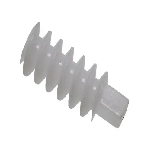
Plastic worm gears possess several notable performance characteristics that make them highly desirable in various industries:
- High torque transmission capability: Plastic worm gears are capable of transmitting high levels of torque, making them suitable for heavy-duty applications.
- Low noise and vibration: Due to their unique design and material properties, plastic worm gears produce minimal noise and vibration during operation, ensuring a smooth and quiet performance.
- Excellent wear resistance: Plastic worm gears are known for their exceptional wear resistance, enabling them to withstand prolonged use without significant deterioration.
- Corrosion resistance: Compared to metal gears, plastic worm gears offer superior corrosion resistance, making them ideal for applications in harsh environments.
- Lightweight and cost-effective: Plastic worm gears are lightweight and cost-effective alternatives to metal gears, offering significant savings in terms of material costs and energy consumption.
Applications in Various Fields
Plastic worm gears find wide-ranging applications in different industries, highlighting their value and importance:
- Building equipment: Plastic worm gears are used in construction machinery and equipment, enabling efficient power transmission in lifting and hoisting systems.
- Industrial machinery: Plastic worm gears are crucial components in industrial machinery, ensuring smooth and precise motion control in conveyor systems and automated production lines.
- Automotive industry: Plastic worm gears are utilized in automotive applications such as power seats, convertible top mechanisms, and windshield wiper systems.
- Textile industry: Plastic worm gears play a vital role in textile machinery, facilitating seamless fabric handling and yarn tension control.
- Marine applications: Plastic worm gears are used in marine equipment, providing reliable power transmission in steering systems, winches, and anchor mechanisms.
Future Trends and Opportunities
The plastic worm gear industry is expected to witness promising growth and opportunities in the coming years. Some suggestions for industry development and prospects include:
- Advancements in material technology: Further research and development into new plastic materials can enhance the performance and durability of plastic worm gears.
- Increased focus on sustainability: As environmental concerns rise, the industry can explore eco-friendly materials and manufacturing processes to meet the growing demand for sustainable solutions.
- Automation and robotics integration: The integration of plastic worm gears in automated systems and robotics can lead to improved efficiency and precision in various industries.
- Strategic partnerships: Collaborations between gear manufacturers and industry leaders can drive innovation and expand market reach.
- Global market expansion: Exploring new markets and expanding international sales efforts can open up new opportunities for the plastic worm gear industry.

Choosing the Right Plastic Worm Gear
Selecting the correct plastic worm gear involves considering several factors:
- Clear identification of requirements: Clearly defining the specific needs and performance expectations is essential in choosing the most suitable plastic worm gear for the application.
- Material selection: The choice of plastic material should take into account factors such as strength, temperature resistance, and chemical compatibility.
- Design optimization: Collaborating with experienced engineers to optimize the design can enhance the gear’s performance and lifespan.
- Supplier and after-sales service: Working with reputable suppliers who offer reliable after-sales support ensures a smooth and hassle-free experience.
- Cost-effectiveness: Balancing the cost and quality of the plastic worm gear is crucial in maximizing value for money.
- Quality control: Ensuring strict quality control measures throughout the manufacturing process guarantees the gear’s reliability and longevity.
Maintaining Plastic Worm Gear
Proper maintenance of plastic worm gears contributes to their longevity and optimal performance:
- Regular equipment inspection: Conducting routine inspections helps identify any signs of wear, damage, or misalignment early on.
- Cleaning and corrosion prevention: Regular cleaning and applying appropriate corrosion prevention methods protect against deterioration caused by environmental factors.
- Lubrication and servicing: Applying suitable lubricants and performing regular servicing ensures smooth operation and minimizes friction.
- Replacement of worn parts: Promptly replacing worn or damaged components helps maintain the gear’s overall performance and prevent further damage.
- Improvement and upgrades: Monitoring advancements in technology and considering gear improvements or upgrades can enhance performance and efficiency.
Why Choose Us?
Here at [Company Name], we are a professional manufacturer and supplier of high-quality plastic worm gears. We offer a wide range of advantages and benefits to our customers:
- Superior product quality: Our plastic worm gears undergo rigorous quality control measures, ensuring exceptional performance and durability.
- Customization options: We provide tailored solutions to meet specific customer requirements, offering gear designs and materials optimized for their applications.
- Advanced manufacturing capabilities: With state-of-the-art production facilities and advanced technologies, we can deliver gears of the highest precision and quality.
- Reliable customer support: Our dedicated customer service team is committed to providing prompt assistance and resolving any inquiries or issues that customers may have.
- Competitive pricing: We offer competitive pricing without compromising on the quality of our gears, providing excellent value for our customers.
Q&A
- Q: How long does the refund process take?
- Q: Can I exchange my plastic worm gear for a different size?
- Q: What is the warranty period for plastic worm gears?
- Q: Do you offer international shipping?
- Q: Are your plastic worm gears suitable for high-temperature applications?
A: The refund process typically takes 3-5 business days from the date we receive the returned product.
A: Yes, we offer exchanges for different sizes of plastic worm gears. Please contact our customer service for further assistance.
A: Our plastic worm gears come with a standard 1-year warranty against manufacturing defects.
A: Yes, we provide international shipping services to cater to customers worldwide. Additional charges may apply.
A: Yes, we offer plastic worm gears specifically designed to withstand high-temperature environments. Please consult our product specifications for more details.
Author: Dream