Product Description
VH9 for 90-120pcs panels single axis horizontal single axis solar tracking system
| Model | VH9 | Square Tube Shaft | 110m |
| 24VDC motor | Yes | Customized | Yes |
| Holdng Torque | 58Kn.m | Tiliting moment Torque | 12Kn.m |
| Output Torque | 6405N.m | Output Speed | 0.571rpm |
VH9 Technology Specification
Coresun – Practical Slewing Drive&Slewing Bearing Promoter.
The slewing drive is a special slewing reduction product derived from the slewing bearing product with high integration and large reduction ratio, simple structure, convenient use and maintenance, because the slewing ring is used as the follower and the frame basis, the slewing ring is used The inner and outer rings respectively realize the input and output of driving power, so that the slewing drive can not only realize 360-degree rotation without a dead point, but also can install a driving power source on the basis of the slewing ring frame at the same time, so its transmission efficiency is high and it is a mechanical transmission The new member of the device family. Because it is essentially a reduction gear, it can also be called a rotary reducer, a turntable reducer or a drive turntable.
Slewing drive can be divided into gear drive and worm gear drive according to the different transmission forms. According to the different closed forms of the transmission pair, it can be divided into open and closed types. The simplest form of slewing drive is used in excavators, tower cranes, etc. The drive turntable on the construction machinery product is the last link of the reduction transmission chain. This kind of rotary drive is an open gear transmission, and its front end needs to be equipped with a planetary reducer with a large reduction ratio as its power input, so it can only be called In order to expand the application range of such products and further improve the convenience of product use and maintenance, the slewing drive with integrated worm gear transmission was developed for the embryonic form of slewing drive. In order to further improve the drive capacity of the product, the enveloping worm drive It is also applied to such products. The rotary drive equipped with an envelope worm not only increases the driving torque, but also improves the driving accuracy. It can also be digitally controlled, so it is widely used in tracking and fine-tuning devices on solar and wind power generation equipment. , In addition, it has good application effects in the fields of robots, radar, low-speed heavy-duty lifting, lifting equipment, and precision CNC turntables.
Slewing drives are perfect for situations requiring both load-holding and rotational torque from the same gearbox.Ttypical applications include solar trackers, wind turbines, satellite and radar dishes, truck cranes, man lifts, utility equipment, hydraulic equipment attachments, oil tool equipment, tire handlers, digger derricks, and automotive lifts.
The performance ranges from 6kNm to 220kNm of holding torque, 200Nm to 63kNm of output torque, 500Nm to 271kNm of overturning moment load capacity, and gearbox reduction ratios of 30:1 up to 156,600:1. The mounting can be done horizontally, vertically, or across a combination of multiple axes.
Vertical installation
It is advised to mount the slewing drives referring to attached drawing upside in solar applications for better protection.
For other applications, the mounting directions shall be based on the evaluation of the protection level and it shall be better for better protection.
Horizontal installation
It is advised to mount the slewing drives upside down on the azimuth axis in solar applications for better protection and add protection for the elevation axis.
For other applications, the mounting directions shall be based on the evaluation of the protection level and it shall be better for better protection.
Tilting Moment Torque: Torque is the load multiplied by distance between the position of load and the center of slewing bearing. If the qorque generated by load and distance is greater than the rated tilting moment torque, slewing drive will be overturned.
Radial load: Load vertical to the axis of slewing bearing
Axial load: Load parallel to the axis of slewing bearing
Holding torque:It is the reverse torque.When the drive is rotating reversely, and parts are not damaged,The maximum torque achieved is called holding torque.
Self-locking: Only when loaded, the slewing drive is not able to reverse rotate and thus called self-locking.
Products Photo
Products Application
Coresun Drive slewing drive VH9 is a good solution to 90-120pcs single axis solar tracker design.
The production is widely export to USA,Canada,Germany,Spain,France,Poland,Turkey,Korea,Australia,South Africa,India, Brazil,Chile…
Products Certificate
Our slewing drive gear motor have arroved by CE and ISO2001 certificate.
CONTACT US
It is sincerely looking CHINAMFG to cooperating with you for and providing you the best quality product & service with all of our heart!
/* March 10, 2571 17:59:20 */!function(){function s(e,r){var a,o={};try{e&&e.split(“,”).forEach(function(e,t){e&&(a=e.match(/(.*?):(.*)$/))&&1
| Feature: | Corrosion-Resistant |
|---|---|
| Step: | Double-Step |
| Openness: | Closed |
| Installation: | Vertical |
| Transmission Form: | Worm |
| Type: | Single-Row Ball |
| Customization: |
Available
| Customized Request |
|---|

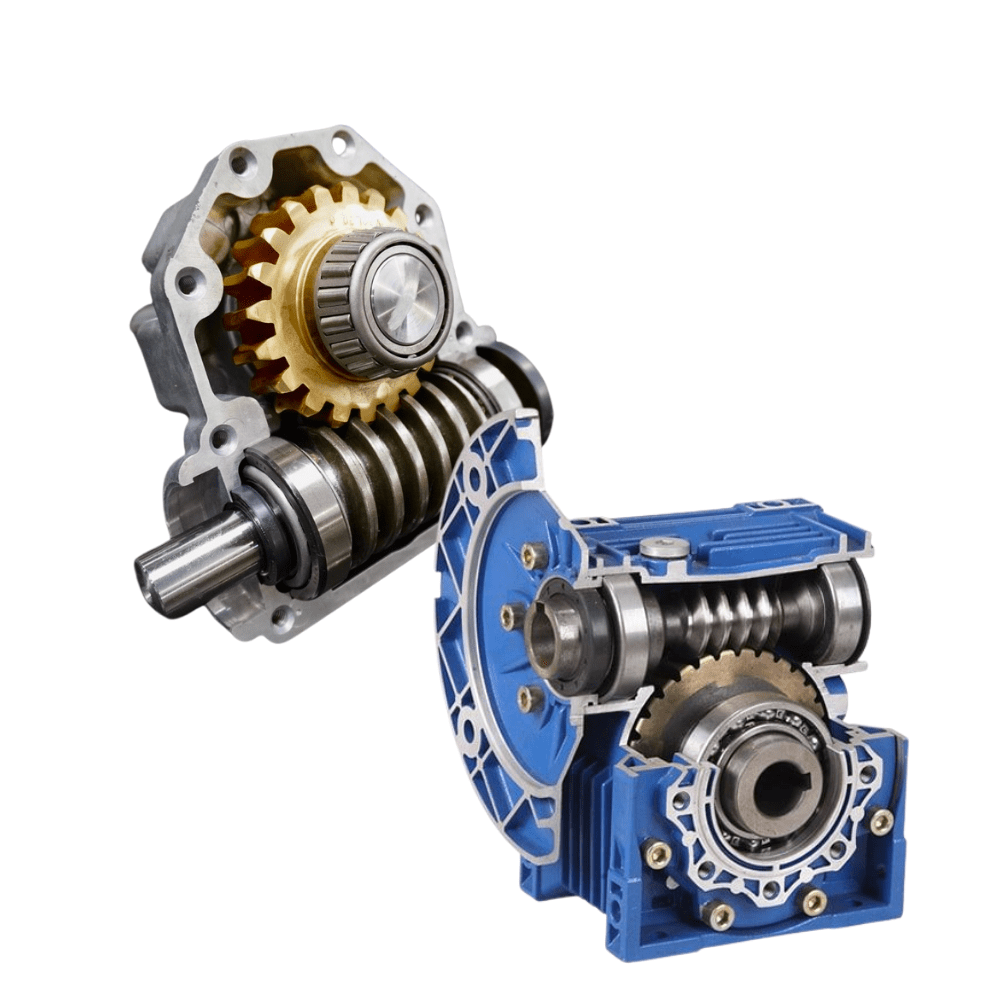
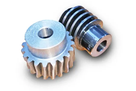
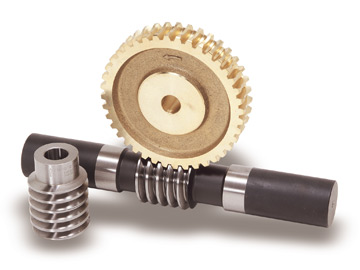
What are the advantages and disadvantages of using a worm gear?
A worm gear offers several advantages and disadvantages that should be considered when selecting it for a specific application. Here’s a detailed explanation of the advantages and disadvantages of using a worm gear:
Advantages of using a worm gear:
- High gear reduction ratio: Worm gears are known for their high gear reduction ratios, which allow for significant speed reduction and torque multiplication. This makes them suitable for applications that require precise motion control and high torque output.
- Compact design: Worm gears have a compact design, making them space-efficient and suitable for applications where size is a constraint. The worm gear’s compactness allows for easy integration into machinery and equipment with limited space.
- Self-locking capability: One of the key advantages of a worm gear is its self-locking property. The angle of the worm thread prevents the reverse rotation of the output shaft, eliminating the need for additional braking mechanisms. This self-locking feature is beneficial for maintaining position and preventing backdriving in applications where holding the load in place is important.
- Quiet operation: Worm gears typically operate with reduced noise levels compared to other gear types. The sliding action between the worm and the worm wheel teeth results in smoother and quieter operation, making them suitable for applications where noise reduction is desired.
- High shock-load resistance: Worm gears have good shock-load resistance due to the sliding contact between the worm and the worm wheel teeth. This makes them suitable for applications that involve sudden or intermittent loads, such as lifting and hoisting equipment.
- Easy installation and maintenance: Worm gears are relatively easy to install and maintain. They often come as a compact unit, requiring minimal assembly. Lubrication maintenance is crucial for optimal performance and longevity, but it is typically straightforward and accessible.
Disadvantages of using a worm gear:
- Lower efficiency: Worm gears tend to have lower mechanical efficiency compared to some other gear types. The sliding action between the worm and the worm wheel teeth generates higher frictional losses, resulting in reduced efficiency. However, efficiency can be improved through careful design, quality manufacturing, and proper lubrication.
- Limited speed capability: Worm gears are not suitable for high-speed applications due to their sliding contact and the potential for heat generation. High speeds can lead to increased friction, wear, and reduced efficiency. However, they excel in low to moderate speed applications where high torque output is required.
- Heat generation: The sliding action between the worm and the worm wheel generates friction, which can result in heat generation. In high-load or continuous-duty applications, this heat buildup can affect the efficiency and longevity of the system. Proper lubrication and heat dissipation measures are necessary to mitigate this issue.
- Less suitable for bidirectional motion: While worm gears offer excellent self-locking capabilities in one direction, they are less efficient and less suitable for bidirectional motion. Reversing the direction of the input or output shaft can lead to increased friction, reduced efficiency, and potential damage to the gear system.
- Lower accuracy in positioning: Worm gears may have lower accuracy in positioning compared to some other gear types, such as precision gear systems. The sliding contact and inherent backlash in worm gears can introduce some degree of positioning error. However, for many applications, the accuracy provided by worm gears is sufficient.
- Potential for wear and backlash: Over time, the sliding action in worm gears can lead to wear and the development of backlash, which is the play or clearance between the worm and the worm wheel teeth. Regular inspection, maintenance, and proper lubrication are necessary to minimize wear and reduce backlash.
When considering the use of a worm gear, it’s essential to evaluate the specific requirements of the application and weigh the advantages against the disadvantages. Factors such as torque requirements, speed limitations, positional stability, space constraints, and overall system efficiency should be taken into account to determine if a worm gear is the right choice.

How do you calculate the efficiency of a worm gear?
Calculating the efficiency of a worm gear involves analyzing the power losses that occur during its operation. Here’s a detailed explanation of the process:
The efficiency of a worm gear system is defined as the ratio of output power to input power. In other words, it represents the percentage of power that is successfully transmitted from the input (worm) to the output (worm wheel) without significant losses. To calculate the efficiency, the following steps are typically followed:
- Measure input power: Measure the input power to the worm gear system. This can be done by using a power meter or by measuring the input torque and rotational speed of the worm shaft. The input power is usually denoted as Pin.
- Measure output power: Measure the output power from the worm gear system. This can be done by measuring the output torque and rotational speed of the worm wheel. The output power is usually denoted as Pout.
- Calculate power losses: Determine the power losses that occur within the worm gear system. These losses can be classified into various categories, including:
- Mechanical losses: These losses occur due to friction between the gear teeth, sliding contact, and other mechanical components. They can be estimated based on factors such as gear design, materials, lubrication, and manufacturing quality.
- Bearing losses: Worm gears typically incorporate bearings to support the shafts and reduce friction. Bearing losses can be estimated based on the bearing type, size, and operating conditions.
- Lubrication losses: Inadequate lubrication or inefficient lubricant distribution can result in additional losses. Proper lubrication selection and maintenance are essential to minimize these losses.
- Calculate efficiency: Once the power losses are determined, the efficiency can be calculated using the following formula:
Efficiency = (Pout / Pin) * 100%
The efficiency is expressed as a percentage, indicating the proportion of input power that is successfully transmitted to the output. A higher efficiency value indicates a more efficient gear system with fewer losses.
It is important to note that the efficiency of a worm gear can vary depending on factors such as gear design, materials, lubrication, operating conditions, and manufacturing quality. Additionally, the efficiency may also change at different operating speeds or torque levels. Therefore, it is advisable to consider these factors and conduct efficiency calculations based on specific gear system parameters and operating conditions.

What is the purpose of a self-locking feature in a worm gear?
A self-locking feature in a worm gear serves the purpose of preventing reverse motion or backdriving of the gear system. When a worm gear is self-locking, it means that the worm can rotate the worm wheel, but the reverse action is hindered or restricted, providing a mechanical holding or braking capability. This self-locking feature offers several advantages and is utilized in various applications. Here are the key purposes of the self-locking feature:
- Mechanical Holding: The self-locking capability of a worm gear allows it to hold a specific position or prevent unintended movement when the worm is not actively driving the system. This is particularly useful in applications where it is necessary to maintain a fixed position or prevent the gear from rotating due to external forces or vibrations. Examples include elevators, lifts, and positioning systems.
- Backdriving Prevention: The self-locking feature prevents the worm wheel from driving the worm in the reverse direction. This is advantageous in applications where it is crucial to prevent a load or external force from causing the gear to rotate backward. For instance, in a lifting mechanism, the self-locking feature ensures that the load remains suspended without requiring continuous power input.
- Enhanced Safety: The self-locking property of a worm gear contributes to safety in certain applications. By preventing unintended or undesired motion, it helps maintain stability and reduces the risk of accidents or uncontrolled movement. This is particularly important in scenarios where human safety or the integrity of the system is at stake, such as in heavy machinery or critical infrastructure.
It’s important to note that not all worm gears are self-locking. The self-locking characteristic depends on the design parameters, specifically the helix angle of the worm’s thread. A higher helix angle increases the self-locking tendency, while a lower helix angle reduces or eliminates the self-locking effect. Therefore, when selecting a worm gear for an application that requires the self-locking feature, it is essential to consider the specific design parameters and ensure that the gear meets the necessary requirements.


editor by CX 2024-02-08